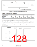
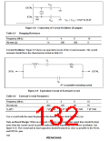
CL1
EXTAL
XTAL
Rd
CL1 = C L2 = 10 pF to 22 pF
CL2
Figure 6.8 Connection of Crystal Oscillator (Example)
Table 6.5 Damping Resistance
Frequency (MHz)
2
4
8
10
0
Rd max (Ω)
1 k
500
200
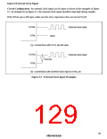
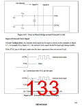
Crystal Oscillator: Figure 6.9 shows an equivalent circuit of the crystal resonator. The crystal
resonator should have the characteristics listed in table 6.6.
CL
L
Rs
XTAL
EXTAL
C0
AT-cut parallel resonating crystal
Figure 6.9 Equivalent Circuit of External Crystal
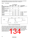
Table 6.6 External Crystal Parameters
Frequency (MHz)
Rs max (Ω)
C0 (pF)
2
4
8
10
70
500
120
80
7 pF max
7 pF max
7 pF max
7 pF max
Use a crystal with the same frequency as the desired system clock frequency (ø).
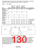
Note on Board Design: When an external crystal is connected, other signal lines should be kept
away from the crystal circuit to prevent induction from interfering with correct oscillation. See
figure 6.10. The crystal and its load capacitors should be placed as close as possible to the XTAL
and EXTAL pins.
102

 RENESAS [ RENESAS TECHNOLOGY CORP ]