Section 19 Band-Gap Circuit, Power-On Reset, and Low-Voltage Detection Circuits
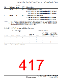
Initial
Bit Name Value
Bit
R/W
Description
1
LVDDE
0
R/W
Voltage-Fall-Interrupt Enable
0: Interrupt on the power-supply voltage falling disabled
1: Interrupt on the power-supply voltage falling enabled
Voltage-Rise-Interrupt Enable
0
LVDUE
0
R/W
0: Interrupt on the power-supply voltage rising disabled
1: Interrupt on the power-supply voltage rising enabled
Notes: 1. Not initialized by an LVDR but initialized by a power-on reset or a watchdog timer reset.
2. For 3.3-V-specification models, this bit 3 of this register is a reserved bit (initial value is
0) and the reset detection voltage is 2.3 V (typ.).
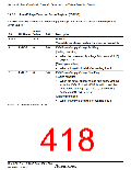
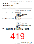
Table 19.1 LVDCR Settings and Select Functions
LVDCR Settings
Select Functions
Low-Voltage- Low-Voltage-
Detection Fall Detection Rise
Power-On
Reset
VDDII
LVDSEL
LVDDE
LVDUE
LVDR
Interrupt
Interrupt
*
1
0
0
0
1
1
0
0
1
√
√
√
√
√
√
√
√
*
*
√
Note:
*
Set these bits if necessary.
Rev. 3.00 Sep. 10, 2007 Page 383 of 528
REJ09B0216-0300

 RENESAS [ RENESAS TECHNOLOGY CORP ]