Section 19 Band-Gap Circuit, Power-On Reset, and Low-Voltage Detection Circuits
19.1
Features
•
BGR circuit
Supplies stable reference voltage covering the entire operating voltage range and the operating
temperature range.
•
•
Power-on reset circuit
Uses an external capacitor to generate an internal reset signal when power is first supplied.
Low-voltage detection circuit
LVDR: Monitors the power-supply voltage, and generates an internal reset signal when the
voltage falls below a given value.
LVDI: Monitors the power-supply voltage, and generates an interrupt when the voltage falls
below or rises above respective given values.
Two detection levels for reset generation voltage are available: when only the LVDR circuit is
used, or when the LVDI and LVDR circuits are both used.
•
Reset source decision
The source of a reset can be decided by reading the reset source decision register in the reset
exception handler.
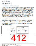
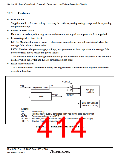
VCLSEL
VCL
Vcc
Step-down circuit
BGR
On-chip
oscillator
RCSTP
VBGR
LVD (low-voltage
detection circuit)
[Legend]
Vcc:
Power supply
VCL:
VBGR:
Internal power supply generated from Vcc by the step-down circuit
Reference voltage from BGR
VCLSEL: Select signal for the source of the on-chip oscillator power supply
RCSTP:
On-chip oscillator stop signal
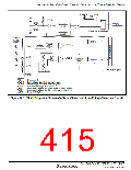
Figure 19.1 Block Diagram around BGR
Rev. 3.00 Sep. 10, 2007 Page 380 of 528
REJ09B0216-0300

 RENESAS [ RENESAS TECHNOLOGY CORP ]