Section 13 Timer Z
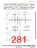
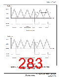
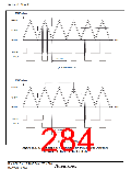
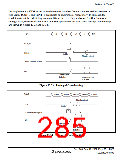
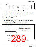
In complementary PWM mode, when the counter switches from up-counter to down-counter or
vice versa, TCNT_0 and TCNT_1 overshoots or undershoots, respectively. In this case, the
conditions to set the IMFA flag in channel 0 and the UDF flag in channel 1 differ from usual
settings. Also, the transfer conditions in buffer operation differ from usual settings. Such timings
are shown in figures 13.33 and 13.34.
TCNT
N-1
N
N+1
N
N-1
GRA_0
N
IMFA
Set to 1
Flag is not set
Buffer transfer signal
GR
Transferred
to buffer
Not transferred
to buffer
Figure 13.33 Timing of Overshooting
TCNT
UDF
H'0001
H'0000
H'FFFF
H'0000
H'0001
Flag is not set
Set to 1
Buffer transfer signal
GR
Transferred
to buffer
Not transferred
to buffer
Figure 13.34 Timing of Undershooting
Rev. 3.00 Sep. 10, 2007 Page 251 of 528
REJ09B0216-0300

 RENESAS [ RENESAS TECHNOLOGY CORP ]