Section 11 Timer B1
11.3
Register Descriptions
The timer B1 has the following registers.
•
•
•
Timer mode register B1 (TMB1)
Timer counter B1 (TCB1)
Timer load register B1 (TLB1)
11.3.1
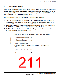
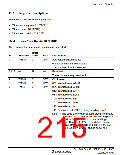
Timer Mode Register B1 (TMB1)
TMB1 selects the auto-reload function and input clock.
Initial
Bit
Bit Name Value
R/W
Description
7
TMB17
0
R/W
Auto-reload function select
0: Interval timer function selected
1: Auto-reload function selected
Reserved
6 to 3
All 1
These bits are always read as 1.
Clock select
2
1
0
TMB12
TMB11
TMB10
0
0
0
R/W
R/W
R/W
000: Internal clock: φ/8192
001: Internal clock: φ/2048
010: Internal clock: φ/512
011: Internal clock: φ/256
100: Internal clock: φ/64
101: Internal clock: φ/16
110: Internal clock: φ/4
111: External event (TMIB1): rising or falling edge*
Note: * The edge of the external event signal is selected
by bit IEG1 in the interrupt edge select register 1
(IEGR1). See section 3.2.1, Interrupt Edge
Select Register 1 (IEGR1), for details. Before
setting TMB12 to TMB10 to 1, IRQ1 in the port
mode register 1 (PMR1) should be set to 1.
Rev. 3.00 Sep. 10, 2007 Page 181 of 528
REJ09B0216-0300

 RENESAS [ RENESAS TECHNOLOGY CORP ]