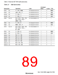
Privileged
Mode Cycles T Bit
Instruction
Operation
Code
STC.L SSR,@–Rn
STC.L SPC,@–Rn
Rn–4 → Rn, SSR → (Rn)
Rn–4 → Rn, SPC → (Rn)
0100nnnn00110011
0100nnnn01000011
√
√
√
2
2
2
—
—
—
STC.L R0_BANK,
Rn–4 → Rn, R0_BANK → (Rn) 0100nnnn10000011
Rn–4 → Rn, R1_BANK → (Rn) 0100nnnn10010011
Rn–4 → Rn, R2_BANK → (Rn) 0100nnnn10100011
Rn–4 → Rn, R3_BANK → (Rn) 0100nnnn10110011
Rn–4 → Rn, R4_BANK → (Rn) 0100nnnn11000011
Rn–4 → Rn, R5_BANK → (Rn) 0100nnnn11010011
Rn–4 → Rn, R6_BANK → (Rn) 0100nnnn11100011
Rn–4 → Rn, R7_BANK → (Rn) 0100nnnn11110011
@–Rn
STC.L R1_BANK,
√
√
√
√
√
√
√
2
2
2
2
2
2
2
—
—
—
—
—
—
—
@–Rn
STC.L R2_BANK,
@–Rn
STC.L R3_BANK,
@–Rn
STC.L R4_BANK,
@–Rn
STC.L R5_BANK,
@–Rn
STC.L R6_BANK,
@–Rn
STC.L R7_BANK,
@–Rn
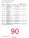
STS
STS
STS
MACH,Rn
MACL,Rn
PR,Rn
MACH → Rn
0000nnnn00001010
0000nnnn00011010
0000nnnn00101010
0100nnnn00000010
0100nnnn00010010
0100nnnn00100010
11000011iiiiiiii
—
—
—
—
—
—
—
1
1
1
1
1
1
8
—
—
—
—
—
—
—
MACL → Rn
PR → Rn
STS.L MACH,@–Rn
STS.L MACL,@–Rn
STS.L PR,@–Rn
TRAPA #imm
Rn–4 → Rn, MACH → (Rn)
Rn–4 → Rn, MACL → (Rn)
Rn–4 → Rn, PR → (Rn)
PC → SPC, SR → SSR,
imm → TRA
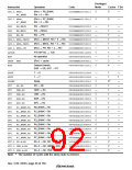
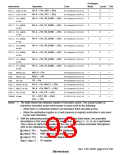
Notes: 1. The table shows the minimum number of execution cycles. The actual number of
instruction execution cycles will increase in cases such as the following:
•
•
When there is contention between an instruction fetch and data access
When the destination register in a load (memory-to-register) instruction is also used
by the next instruction
2. With the addressing modes using displacement (disp) listed below, the assembler
descriptions in this manual show the value before scaling (×1, ×2, or ×4) is performed.
This is done to clarify the operation of the chip. For the actual assembler descriptions,
refer to the individual assembler notation rules.
@ (disp:4, Rn) ; Register-indirect with displacement
@ (disp:8, Rn) ; GBR-indirect with displacement
@ (disp:8, PC) ; PC-relative with displacement
disp:8, disp:12 ; PC-relative
Rev. 5.00, 09/03, page 49 of 760

 RENESAS [ RENESAS TECHNOLOGY CORP ]