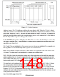
Address array (ways 0−3)
Data array (ways 0−3)
LRU
Entry 0
Entry 1
0
1
0
1
V
U Tag address
LW0
LW1
LW2
LW3
.
.
.
.
.
.
.
.
.
.
.
.
.
.
.
.
.
.
Entry 255
255
255
24 (1 + 1 + 22) bits
128 (32 × 4) bits
6 bits
LW0−LW3: Longword data 0−3
Figure 5.1 Cache Structure
Address Array: The V bit indicates whether the entry data is valid. When the V bit is 1, data is
valid; when 0, data is not valid. The U bit indicates whether the entry has been written to in write-
back mode. When the U bit is 1, the entry has been written to; when 0, it has not. The address tag
holds the physical address used in the external memory access. It is composed of 22 bits (address
bits 31–10) used for comparison during cache searches.
In the SH7709S, the top three of 32 physical address bits are used as shadow bits (see section 10,
Bus State Controller (BSC)), and therefore in a normal replace operation the top three bits of the
tag address are cleared to 0.
The V and U bits are initialized to 0 by a power-on reset, but are not initialized by a manual reset.
The tag address is not initialized by either a power-on or manual reset.
Data Array: Holds a 16-byte instruction or data. Entries are registered in the cache in line units
(16 bytes). The data array is not initialized by a power-on or manual reset.
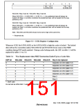
LRU: With the 4-way set associative system, up to four instructions or data with the same entry
address (address bits 11–4) can be registered in the cache. When an entry is registered, the LRU
shows which of the four ways it is recorded in. There are six LRU bits, controlled by hardware. A
least-recently-used (LRU) algorithm is used to select the way.
The way that is to be replaced on a cache miss is determined by the 6-bit LRU. Table 5.2 shows
the correspondence between the LRU bits and the way to be replaced when the cache-lock
function is not used (when the cache-lock function is used, refer to section 5.2.2, Cache Control
Register 2 (CCR2)). If a bit pattern other than those listed in table 5.2 is set in the LRU bits by
software, the cache will not function correctly. When modifying the LRU bits by software, set one
of the patterns listed in table 5.2.
Rev. 5.00, 09/03, page 104 of 760

 RENESAS [ RENESAS TECHNOLOGY CORP ]