19.4
INTC Operation
19.4.1
Interrupt Operation Sequence
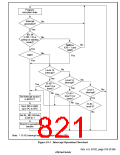
The sequence of operations when an interrupt is generated is described below. Figure 19.3 shows a
flowchart of the operations.
1. The interrupt request sources send interrupt request signals to the interrupt controller.
2. The interrupt controller selects the highest-priority interrupt from the interrupt requests sent,
according to the priority levels set in interrupt priority registers A to C (IPRA–IPRC). Lower-
priority interrupts are held pending. If two of these interrupts have the same priority level, or if
multiple interrupts occur within a single module, the interrupt with the highest priority
according to table 19.5, Interrupt Exception Handling Sources and Priority Order, is selected.
3. The priority level of the interrupt selected by the interrupt controller is compared with the
interrupt mask bits (I3–I0) in the status register (SR) of the CPU. If the request priority level is
higher that the level in bits I3–I0, the interrupt controller accepts the interrupt and sends an
interrupt request signal to the CPU.
4. The CPU accepts an interrupt at a break between instructions.
5. The interrupt source code is set in the interrupt event register (INTEVT).
6. The status register (SR) and program counter (PC) are saved to SSR and SPC, respectively.
The R15 contents at this time are saved in SGR.
7. The block bit (BL), mode bit (MD), and register bank bit (RB) in SR are set to 1.
8. The CPU jumps to the start address of the interrupt handler (the sum of the value set in the
vector base register (VBR) and H'00000600).
The interrupt handler may branch with the INTEVT register value as its offset in order to identify
the interrupt source. This enables it to branch to the handling routine for the particular interrupt
source.
Notes: 1. The interrupt mask bits (I3–I0) in the status register (SR) are not changed by
acceptance of an interrupt in the SH7750 Series.
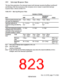
2. The interrupt source flag should be cleared in the interrupt handler. To ensure that an
interrupt request that should have been cleared is not inadvertently accepted again, read
the interrupt source flag after it has been cleared, then wait for the interval shown in
table 19.7 (Time for priority decision and SR mask bit comparison) before clearing the
BL bit or executing an RTE instruction.
3. For some interrupt sources, their interrupt masks (INTMSK00) must e cleared using
the INTMSKCLR00 register.
Rev. 6.0, 07/02, page 768 of 986

 RENESAS [ RENESAS TECHNOLOGY CORP ]