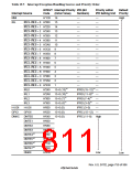
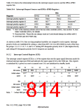
Table 19.6 shows the relationship between the interrupt request sources and the IPRA–IPRD
register bits.
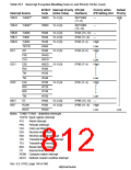
Table 19.6 Interrupt Request Sources and IPRA–IPRD Registers
Bits
Register
15–12
TMU0
WDT
GPIO
IRL0
11–8
7–4
3–0
Interrupt priority register A
Interrupt priority register B
Interrupt priority register C
Interrupt priority register D
TMU1
TMU2
SCI1
SCIF
IRL2
RTC
1
2
*
*
REF
Reserved
H-UDI
IRL3
DMAC
IRL1
3
*
Notes: *1 REF is the memory refresh unit in the bus state controller (BSC). See section 13, Bus
State Controller (BSC), for details.
*2 Reserved bits: These bits are always read as 0 and should always be written with 0.
*3 SH7750S and SH7750R only
As shown in table 19.6, four on-chip peripheral modules are assigned to each register. Interrupt
priority levels are established by setting a value from H'F (1111) to H'0 (0000) in each of the four-
bit groups: 15–12, 11–8, 7–4, and 3–0. Setting H'F designates priority level 15 (the highest level),
and setting H'0 designates priority level 0 (requests are masked).
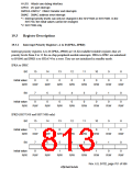
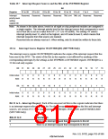
19.3.2
Interrupt Control Register (ICR)
The interrupt control register (ICR) is a 16-bit register that sets the input signal detection mode for
external interrupt input pin NMI and indicates the input signal level at the NMI pin. This register
is initialized by a power-on reset or manual reset. It is not initialized in standby mode.
Bit:
Bit name:
Initial value:
R/W:
15
NMIL
0/1*
R
14
MAI
0
13
—
0
12
—
0
11
—
0
10
—
0
9
NMIB
0
8
NMIE
0
R/W
—
—
—
—
R/W
R/W
Bit:
Bit name:
Initial value:
R/W:
7
IRLM
0
6
—
0
5
—
0
4
—
0
3
—
0
2
—
0
1
—
0
0
—
0
R/W
—
—
—
—
—
—
—
Note: * 1 when NMI pin input is high, 0 when low.
Rev. 6.0, 07/02, page 762 of 986

 RENESAS [ RENESAS TECHNOLOGY CORP ]