APPENDIX
Appendix 9. M37906M4C-XXXFP electrical characteristics
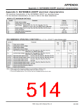
PERIPHERAL DEVICE INPUT/OUTPUT TIMING
(VCC = 5 V±0.5 V, VSS = 0 V, Ta = –20 to 85 °C, f(fsys) = 20 MHz, unless otherwise noted)
For limits depending on f(fsys), their calculation formulas are shown below. Also, the values at f(fsys) = 20 MHz are shown in ( ).
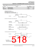
Timer A input (Count input in event counter mode)
Limits
Symbol
Parameter
Unit
Min.
80
Max.
tc(TA)
TAjIN input cycle time
ns
ns
ns
tw(TAH)
tw(TAL)
TAjIN input high-level pulse width
TAjIN input low-level pulse width
40
40
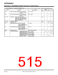
Timer A input (Gating input in timer mode)
Limits
Symbol
Parameter
Unit
ns
Min.
16 × 109
f(fsys)
8 × 10⁹
f(fsys)
8 × 10⁹
f(fsys)
Max.
(800)
f(fsys)
≤
≤
≤
20 MHz
20 MHz
20 MHz
tc(TA)
TAjIN input cycle time
(400)
(400)
ns
f(fsys)
f(fsys)
tw(TAH)
tw(TAL)
TAjIN input high-level pulse width
TAjIN input low-level pulse width
ns
Note :The TAjIN input cycle time requires 4 or more cycles of a count source. The TAjIN input high-level pulse width and the TAjIN input low-level pulse width
respectively require 2 or more cycles of a count source. The limits in this table are applied when the count source = f2 at f(fsys)
≤ 20 MHz.
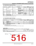
Timer A input (External trigger input in one-shot pulse mode)
Limits
Symbol
Parameter
Unit
ns
Min.
8 × 10⁹
f(fsys)
Max.
tc(TA)
TAjIN input cycle time
f(fsys) ≤ 20 MHz
(400)
tw(TAH)
tw(TAL)
TAjIN input high-level pulse width
TAjIN input low-level pulse width
80
80
ns
ns
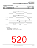
Timer A input (External trigger input in pulse width modulation mode)
Symbol Parameter
Limits
Unit
Min.
80
Max.
tw(TAH)
tw(TAL)
TAjIN input high-level pulse width
TAjIN input low-level pulse width
ns
ns
80
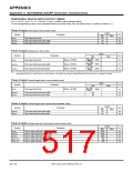
Timer A input (Up-down input and Count input in event counter mode)
Limits
Symbol
Parameter
Unit
Min.
2000
1000
1000
400
Max.
tc(UP)
TAjOUT input cycle time
ns
ns
ns
ns
ns
tw(UPH)
TAjOUT input high-level pulse width
TAjOUT input low-level pulse width
TAjOUT input setup time
tw(UPL)
tsu(UP-TIN)
th(TIN-UP)
TAjOUT input hold time
400
7906 Group User’s Manual Rev.2.0
20-112

 RENESAS [ RENESAS TECHNOLOGY CORP ]