APPENDIX
Appendix 9. M37906M4C-XXXFP electrical characteristics
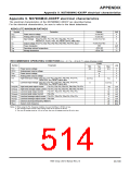
Appendix 9. M37906M4C-XXXFP electrical characteristics
The electrical characteristics of the M37906M4C-XXXFP are described below.
For the electrical characteristics, be sure to refer to the latest datasheets.
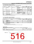
ABSOLUTE MAXIMUM RATINGS
Ratings
–0.3 to 6.5
Parameter
Unit
V
Symbol
Power source voltage
VCC
–0.3 to 6.5
Analog power source voltage
V
AVCC
VI
–0.3 to VCC+0.3
Input voltage P10–P17, P20–P27, P50–P57, P60–P65, P70–P74,
P6OUTCUT, VCONT, VREF, XIN, RESET, BYTE, MD0, MD1
V
–0.3 to VCC+0.3
300
Output voltage P10–P17, P20–P27, P50–P57, P60–P65, P70–P74, XOUT
Power dissipation
V
mW
°C
VO
Pd
–20 to 85
–40 to 150
Operating ambient temperature
Topr
Tstg
Storage temerature
°C
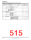
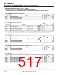
RECOMMENDED OPERATING CONDITIONS (Vcc = 5 V, Ta = –20 to 85 °C, unless otherwise noted)
Limits
Symbol
Parameter
Unit
Typ.
5.0
VCC
0
Min.
4.5
Max.
5.5
VCC
AVCC
VSS
Power source voltage
V
V
V
V
V
Analog power source voltage
Power source voltage
AVSS
VIH
Analog power source voltage
0
High-level input voltage P10–P17, P20–P27, P50–P57, P60–P65, P70–P74,
P6OUTCUT, XIN, RESET, MD0, MD1
0.8 Vcc
0
Vcc
VIL
Low-level input voltage P10–P17, P20–P27, P50–P57, P60–P65, P70–P74,
P6OUTCUT, XIN, RESET, MD0, MD1
0.2 VCC
V
IOH(peak)
IOH(avg)
IOL(peak)
IOL(peak)
IOL(avg)
IOL(avg)
f(XIN)
High-level peak output current
P10–P17, P20–P27, P50–P57, P60–P65, P70–P74
–10
–5
10
20
5
mA
mA
High-level average output current P10–P17, P20–P27, P50–P57, P60–P65, P70–P74
Low-level peak output current
Low-level peak output current
P10–P17, P20–P27, P50–P57, P70–P74
P60–P65
mA
mA
Low-level average output current P10–P17, P20–P27, P50–P57, P70–P74
Low-level average output current P60–P65
External clock input frequency (Note 1)
mA
15
20
20
mA
MHz
MHz
f(fsys)
System clock frequency
Notes 1: When using the PLL frequency multiplier, be sure that f(fsys) = 20 MHz or less.
2: The average output current is the average value of an interval of 100 ms.
3: The sum of IOL(peak) must be 110 mA or less, the sum of IOH(peak) must be 80 mA or less.
7906 Group User’s Manual Rev.2.0
20-109

 RENESAS [ RENESAS TECHNOLOGY CORP ]