INPUT/OUTPUT PINS
5.1 Overview, 5.2 Programmable I/O ports
5.1 Overview
Input/output pins (hereafter called I/O pins) have functions as programmable I/O port pins, internal peripheral
devices’s I/O pins, etc.
For the basic functions of each I/O pin, refer to section “1.3 Pin description.” For the I/O functions of the
internal peripheral devices, refer to relevant sections of each internal peripheral device.
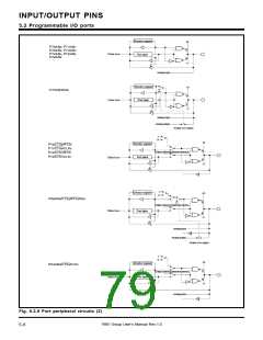
This chapter describes the programmable I/O ports and examples of handling unused pins.
5.2 Programmable I/O ports
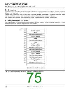
The programmable I/O ports have direction registers and port registers in the SFR area. Figure 5.2.1 shows
the memory map of direction registers and port registers.
Addresses
3
16
16
16
16
16
16
16
16
16
16
16
16
16
Port P1 register
(Note)
4
5
Port P1 direction register
Port P2 register
6
7
(Note)
8
Port P2 direction register
(Note)
9
A
B
C
D
E
F
Port P4 register
Port P5 register
Port P4 direction register
Port P5 direction register
Port P6 register
Port P7 register
1016
1116
1216
1316
1416
Port P6 direction register
Port P7 direction register
Port P8 register
(Note)
Port P8 direction register
Note: Do not write to this address.
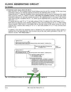
Fig. 5.2.1 Memory map of direction registers and port registers
7905 Group User’s Manual Rev.1.0
5-2

 RENESAS [ RENESAS TECHNOLOGY CORP ]