INTERRUPTS
[Precautions for interrupts]
[Precautions for interrupts]
1. In order to change the interrupt priority level select bits (bits 0 to 2 at addresses 6E16 to 7F16, F116, F216
,
F516 to F916, FD16 to FF16), 2 to 7 cycles of fsys are required after execution of a write instruction until
change of the interrupt priority level. Therefore, when the interrupt priority level of a certain interrupt
source is repeatedly changed in a very short time, which consists of a few instructions, it is necessary
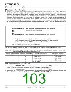
to reserve the time required for the change by software. Figure 6.10.6 shows a program example to
reserve the time required for the change. Note that the time required for the change depends on the
contents of the interrupt priority detection time select bits (bits 4 and 5 at address 5E16). Table 6.10.2 lists
the correspondence between the number of instructions inserted in Figure 6.10.6 and the interrupt priority
detection time select bits.
:
; Write instruction for the interrupt priority level select bits
MOVMB 00XXH, #0XH
; Inserted NOP instruction (Note)
NOP
;
NOP
;
NOP
; Write instruction for the interrupt priority level select bits
MOVMB 00XXH, #0XH
:
Note: Except a write instruction for address XX16, any instruction which has the same
cycles as the NOP instruction can also be inserted, instead of the NOP instruction.
For the number of inserted NOP instructions, see Table 6.10.2.
XX: any of 6E to 7F, F1, F2, F5 to F9, and FD to FF
Fig. 6.10.6 Program example to reserve time required for change of interrupt priority level
Table 6.10.2 Correspondence between number of instructions to be inserted in Figure 6.10.6 and
interrupt priority detection time select bits
Interrupt priority level
detection time
Number of inserted
NOP instructions
7 or more
Interrupt priority detection time select bits (Note)
b5
0
b4
0
7 cycles of fsys
0
1
4 cycles of fsys
2 cycles of fsys
Do not select.
4 or more
1
0
2 or more
1
1
Note: We recommend [b5 = “1”, b4 = “0”].
2. When using pin P4OUTCUT/INT
0
as an input pin of an external interrupt (pin INT
0
4
), be sure to use port pins
), be sure to use port pins
P4 to P4 in the input mode. (Refer to section “5.2.3 Pin P4OUTCUT/INT
0
7
0
.”)
3. When using pin P6OUTCUT/INT
4
as an input pin of an external interrupt (pin INT
P6
0
to P6
7
in the input mode. (Refer to section “5.2.4 Pin P6OUTCUT/INT
4
.”)
7905 Group User’s Manual Rev.1.0
6-22

 RENESAS [ RENESAS TECHNOLOGY CORP ]