ALC5642-VF
Datasheet
Slave Mode
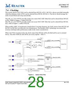
Under slave mode BCLK and LRCK are configured as input. The SYSCLK can be input from MCLK,
and BCLK can be synchronous or asynchronous to MCLK. If the SYSCLK is selected from BCLK, the
internal PLL should generate 256*FS by BCLK. And the driver should set each divider to arrange the
clock distribution. Refer to Figure5. Audio Clock Tree, for details.
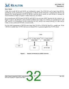
If an asynchronous MCLK input for BCLK and LRCK, you can turn ASRC function for this situation. As
Figure 6 shown, the MCLK is from external oscillator that clock is no relation (or asynchronous) with
SOC and BT or 3G BaseBand. For the connection for SOC and BT can connect directly to Codec and let
Codec as slave mode and SOC/BT as master mode.
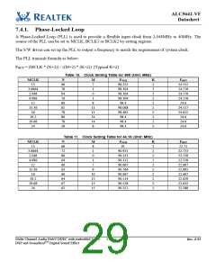
For the clock requirement of MCLK must large than 512*FS as SYSCLK that FS is sample rate. If the
MCLK is smaller than 512*FS, that can use internal PLL to generate higher than 512*FS clock.
Codec
I2S-1 as Slave Mode I2S-1 as Slave Mode
MCLK
With ASRC
With ASRC
OSC
SOC
BT/3G BB
Figure 7. System Connection for ASRC Function
Multi-Channel Audio Hub/CODEC with embedded Voice
DSP and SounzRealTM Digital Sound Effect
20
Rev. 0.93

 REALTEK [ Realtek Semiconductor Corp. ]