ALC5642-VF
Datasheet
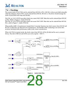
7.4. Clocking
The system clock of ALC5642 can be selected from MCLK or PLL. MCLK is always provided externally
while the reference clock of PLL can be selected from MCLK, BCLK1/2. The driver should arrange the
clock of each block and setup each divider.
The Clk_sys_i2s1=256*Fs provides clocks into stereo DAC/ADC filter that can be selected from MCLK
or PLL. Refer to Figure 5. Audio SYSCLK
The Clk_sys_i2s2=256*Fs provides clocks into mono DAC/ADC filter that can be selected from MCLK,
PLL, refer to Figure 5. Audio SYSCLK
When enable ASRC (Asynchronous Sample Rate Converter) function, the clock sources from MCLK and
BCLK1 (or BCLK2) are allowed to be asynchronous. The Realtek ASRC technology can ensure data
accuracy and keep audio performance under clock source asynchronous.
When ALC5642 at master mode, the clock source from MCLK will be divided and be sent to external
device. The ratio of BCLK and LRCK can set by register – MX-73.
MX80[15:14]
MCLK
MX73[14:12]
Clk_sys_i2s1(256FS)
MX80[3]
DIV_F1
MX80[13:12]
÷2
MCLK
Inter. Clock
(Slave)
(Slave)
System Clock
PLL
PLL
MX73[10:8]
MX81 & MX82
Clk_sys_i2s2(256FS)
DIV_F2
MX70[15]
BCLK1(Master)
LRCK1(Master)
BCLK1
LRCK1
Master Mode
LRCK/BCLK
Filter_Clk1 (256FS)
Ratio
MX73[15]
MX70[15]
LRCK1(Slave)
MX71[15]
BCLK2(Master)
BCLK2
LRCK2
Master Mode
LRCK/BCLK
Clk_sys_i2s2(256FS)
Ratio
MX73[11]
MX71[15]
LRCK2(Master)
LRCK2(Slave)
Figure 6.
Audio Clock Tree
Multi-Channel Audio Hub/CODEC with embedded Voice
DSP and SounzRealTM Digital Sound Effect
16
Rev. 0.93

 REALTEK [ Realtek Semiconductor Corp. ]