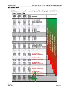
WM72016 – Secure F-RAM with Gen-2 RFID and Serial Port
register they are locking. As such, attention needs to be placed on how the contents of the Control/Status word
are written when the register is not completely unlocked.
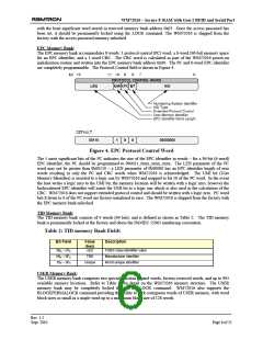
Table 4: Control/Status Word Locking
LOCK PERMA- Description
LOCK
0
0
0
1
Register unlocked. All control bits, including the LOCK and PERMALOCK bits can
be written to from the OPEN or SECURED states.
Register permanently unlocked. All control bits can be written from the OPEN or
SECURED states. The LOCK and PERMALOCK bits must be set to logic values 0
and 1 respectively when writing the Control/Status word.
1
0
Register locked. All control bits can be written to only from the SECURED state.
The register cannot be written to in the OPEN state. The LOCK and PERMALOCK
bits must be set to logic values 1 and 0 respectively when writing the Control/Status
word.
1
1
Register permanently locked. The register cannot be written in any circumstance.
Block Write Enable: The BLKWREN control bit enables usage of the WM72016 custom command
BLOCKWRITE. The BLKWREN parameter is internally updated during power-on WM72016 initialization.
In the event the host application toggles the state of BLKWREN either through the Gen2 or serial interfaces, a
WM72016 power cycle is required to reflect the change.
Block Size: The 3 BLKSIZ[2:0] control bits adjust the USER memory block sizes as shown in Table 5:. This
provides a host application the ultimate flexibility in determining a balance between the USER memory
requirements and the granularity of the number of USER memory words per block. The larger the granularity
of the block size, the greater amount of available USER memory. The effect of the block size on available
USER memory is shown in Table 1:. The total number of USER memory words available as a function of the
block size is shown in Table 5: below. It is of utmost importance that the 3-bit block size is not modified once
set, which would result in corruption of block permalock status bits.
Table 5: Available USER Memory
Memory
BLKSIZ
Words/Block
Free USER Memory
(words)
931
16k
16k
16k
16k
16k
16k
16k
16k
000
001
010
011
100
101
110
110
1
2
963
4
979
8
987
16
32
64
128
991
993
993
993
Wrap Status: The WRPSTAT status bit is asserted to a logic one when the following conditions are true:
(a) WRPEN=1, AUTOINCR=1 and AUTOLOCK=0,
(b) The contents of the Working Stored Address register address the last USER memory location, and
(c) An unaddressed WRITE command is received.
The WRPSTAT can be cleared by the RFID interrogator by writing a logic zero to the WRPSTAT bit.
Wrap Enable: Asserting the WRPEN control bit to a logic one enables the USER memory wrapping feature.
The wrap enable feature allows the stored address pointer to wrap back to the factory-set initial stored address
value of 0x006. In this manner, the WM72016 memory acts as a circular buffer. Clearing the WRPEN control
bit disables wrapping resulting in a write-once memory. In this case, when the Working Stored Address
reaches the end of user memory, no additional unaddressed write cycles will be possible. The WRPEN and
AUTOLOCK control bits are mutually exclusive – only one of the two control bits may be asserted at any
given time.
Rev. 1.2
Sept. 2010
Page 8 of 21

 RAMTRON [ RAMTRON INTERNATIONAL CORPORATION ]