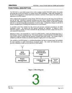
WM72016 – Secure F-RAM with Gen-2 RFID and Serial Port
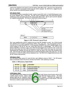
CONTROL/STATUS REGISTER
Accessing the unique features of WM72016 is accomplished through the Control/Status register in F-RAM
non-volatile memory. The register is located at physical address 0x016 or USER memory address 0x002.
The Control/Status word register is organized as shown in Table 3: below. Care should be exercised when
writing the Control/Status register word if it is to remain unlocked.
Table 3: Control/Status Word Register
Bit Mnemonic
Function
Initial
Value
0
15 LOCK
Memory locking of this register.
14 PERMALOCK
0
LOCK
PERMALOCK
DESCRIPTION
0
0
1
0
1
0
Register unlocked
Register permanently unlocked
Register writeable only from the
SECURED state
1
1
Register permanently locked
13 RFU
12 RFU
11 RFU
10 RFU
Reserved for future use
Reserved for future use
Reserved for future use
Reserved for future use
Reserved for future use
Reserved for future use
0
0
0
0
0
0
1
1
1
0
9
8
7
6
5
4
RFU
RFU
BLKWREN
BLKSIZ[2]
BLKSIZ[1]
BLKSIZ[0]
Enables use of the custom command BLOCKWRITE.
USER memory block size.
BLKSIZ[2:0]
000
# words
BLKSIZ[2:0]
100
# words
16
1
2
4
8
001
101
32
010
011
110
111
64
128
3
2
WRPSTAT
WRPEN
Indicates if the Working Stored Address has wrapped.
0
0
Logic State
Description
0
1
Wrapping has not occurred
Wrapping has occurred at least once
Enables wrapping of the Working Stored Address when it reaches the
top of logical memory.
Logic State
0
1
Description
DISABLE memory wrapping
ENABLE memory wrapping.
1
0
AUTOLOCK
AUTOINCR
Enable Automatic Locking of all user memory between the start of USER
memory and the Working Stored Address register.
0
0
Logic State
0
1
Description
Auto-lock DISABLED
Auto-lock ENABLED
Enable the Working Stored Address word to Auto-Increment when
performing an unaddressed write cycle.
Logic State
Description
0
1
DISABLE auto-increment of stored address register
ENABLE auto-increment of stored address register
Upon power up, WM72016’s control logic reads the control word out of memory and configures itself
accordingly. User applications may change the control word as needed providing the register has not been
permanently locked. The Control/Status word may be read by the application at any time.
Register Locking: The LOCK and PERMALOCK control bits are implemented in a similar manner as locking
bits used for Gen2 memory bank locking with the exception that the lock control bits are incorporated into the
Rev. 1.2
Sept. 2010
Page 7 of 21

 RAMTRON [ RAMTRON INTERNATIONAL CORPORATION ]