QN8007B/8007LB
3.1 I2S Interface Timing
Note: The term 'receiver' as described below is from the QN8007's point of view.
Either the QN8007 or the external device can act as the system master by providing the necessary clock signals. The slave
will usually derive its internal clock signal from an external clock input. This means, taking into account the propagation
delay between the master clock and the data and/or word-select signals, that the total delay is simply the sum of:
The delay between the external (master) clock and slave’s internal clock;
The delay between the internal clock and the data and/or word-select signals.
For data and word-select inputs, the external to internal clock delay is of no consequence because it only lengthens the
effective set-up time (see Figure 6:). The major part of the time margin is to accommodate the difference between the
propagation delay of the transmitter, and the time required to set up the receiver. All timing requirements are specified
relative to the clock period or to the minimum allowed clock period of a device. This means that higher data rates can be
used in the future.
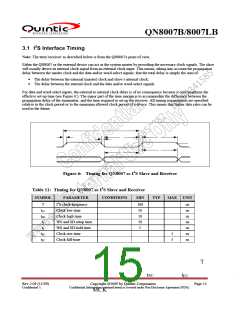
Figure 6: Timing for QN8007 as I2S Slave and Receiver
Table 11: Timing for QN8007 as I2S Slave and Receiver
SYMBOL
PARAMETER
CONDITIONS
MIN
TYP
MAX UNIT
T
tLC
tHC
ts
I2S clock frequency
Clock low time
100
10
10
10
5
ns
ns
ns
ns
ns
Clock high time
WS and SD setup time
WS and SD hold time
Clock rise-time
th
tRC
tFC
5
5
ns
ns
Clock fall-time
Rev 2.09 (11/09)
Confidential A
Copyright ©2009 by Quintic Corporation
Confidential Information contained herein is covered under Non-Disclosure Agreement (NDA).
Page 15

 QUANTUM [ QUANTUM RESEARCH GROUP ]