TOP252-262
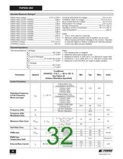
Absolute Maximum Ratings(2)
DRAIN Peak Voltage..................................................................-0.3 V to 700 V VOLTAGE MONITOR Pin Voltage............................................-0.3 V to 9 V
DRAIN Peak Current: TOP252................................................................0.68 A CURRENT LIMIT Pin Voltage................................................-0.3 V to 4.5 V
DRAIN Peak Current: TOP253.................................................................1.37 A MULTI-FUNCTION Pin Voltage .................................................-0.3 V to 9 V
DRAIN Peak Current: TOP254................................................................2.08 A FREQUENCY Pin Voltage ...........................................................-0.3 V to 9 V
DRAIN Peak Current: TOP255.................................................................2.72 A Storage Temperature ...........................................................-65 °C to 150 °C
DRAIN Peak Current: TOP256................................................................4.08 A Operating Junction Temperature................................... -40 °C to 150 °C
Lead Temperature(1) ......................................................................................260 °C
DRAIN Peak Current: TOP257................................................................5.44 A
DRAIN Peak Current: TOP258................................................................6.88 A
DRAIN Peak Current: TOP259................................................................. 7.73 A Notes:
DRAIN Peak Current: TOP260................................................................9.00 A 1. 1/16 in. from case for 5 seconds.
DRAIN Peak Current: TOP261............................................................... 11.10 A 2. Maximum ratings specified may be applied one at a time
DRAIN Peak Current: TOP262............................................................... 11.10 A
CONTROL Voltage............................................................................-0.3 V to 9 V
CONTROL Current......................................................................................100 mA
without causing permanent damage to the product. Exposure
to Absolute Maximum Rating conditions for extended periods
of time may affect product reliability.
Thermal Impedance
Thermal Impedance: Y Package:
Notes:
(θJA) ..................................................................80 °C/W(1) 1. Free standing with no heatsink.
(θJC) ....................................................................2 °C/W(2) 2. Measured at the back surface of tab.
3. Soldered to 0.36 sq. in. (232 mm2), 2 oz. (610 g/m2) copper clad.
P, G and M Packages:
4. Soldered to 1 sq. in. (645 mm2), 2 oz. (610 g/m2) copper clad.
(θJA) .........................................70 °C/W(3); 60 °C/W(4)
(θJC) .................................................................11 °C/W(5) 5. Measured on the SOURCE pin close to plastic interface.
E/L Package:
(θJA) ................................................................105 °C/W(1)
(θJC) ....................................................................2 °C/W(2)
Conditions
SOURCE = 0 V; TJ = -40 to 125 °C
Parameter
Symbol
Min
Typ
Max
Units
See Figure 54
(Unless Otherwise Specified)
Control Functions
FREQUENCY Pin
Connected to SOURCE
119
132
145
TOP252-258Y
TOP255-262L
TOP252-262E
Switching Frequency
in Full Frequency
Mode (average)
FREQUENCY Pin
fOSC
TJ = 25 °C
kHz
Connected to CONTROL
TOP252-258Y
59.4
59.4
66
66
72.6
72.6
TOP255-262L
TOP252-262E
TOP252-258P/G/M
TOP259-261Y
132 kHz Operation
66 kHz Operation
5
2.5
Frequency Jitter
kHz
Hz
Δf
Frequency Jitter
Modulation Rate
fM
250
IV ≤ IV(DC) or IM ≤ IM(DC) or
VV, VM = 0 V
75
30
78
83
Maximum Duty Cycle
DCMAX
IC = ICD1
%
IV or IM = 95 μA
Soft-Start Time
PWM Gain
tSOFT
TJ = 25 °C
17
ms
TOP252-255
TOP256-258
TOP259-262
-31
-27
-25
-25
-22
-20
-20
-17
-15
DCreg
TJ = 25 °C
%/mA
PWM Gain
Temperature Drift
See Note A
-0.01
%/mA/°C
mA
TOP252-255
0.9
1.0
1.1
1.5
1.6
1.7
2.1
2.2
2.4
External Bias Current
IB
66 kHz Operation
TOP256-258
TOP259-262
32
Rev. F 01/09
www.powerint.com

 POWERINT [ Power Integrations ]