TOP242-249
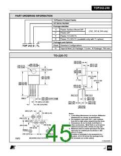
PART ORDERING INFORMATION
TOPSwitch Product Family
GX Series Number
Package Identifier
G
P
Plastic Surface Mount DIP
(242, 243 & 244 only)
Plastic DIP
Y
Plastic TO-220-7C
R
Plastic TO-263-7C (available only with TL option)
Package/Lead Options
Blank Standard Configurations
TOP 242 G - TL
TL
Tape & Reel, (G Package: 1 k min., R Package: 750 min.)
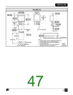
TO-220-7C
.165 (4.19)
.185 (4.70)
.400 (10.16)
.415 (10.54)
.045 (1.14)
.055 (1.40)
.146 (3.71)
.156 (3.96)
.108 (2.74) REF
.236 (5.99)
.260 (6.60)
+
.570 (14.48)
REF.
.467 (11.86)
.487 (12.37)
7° TYP.
.670 (17.02)
REF.
.860 (21.84)
.880 (22.35)
.095 (2.41)
.115 (2.92)
PIN 1 & 7
PIN 2 & 4
.026 (.66)
.032 (.81)
.040 (1.02)
.060 (1.52)
PIN 1
.010 (.25) M
.015 (.38)
.020 (.51)
.040 (1.02)
.060 (1.52)
.050 (1.27) BSC
.150 (3.81) BSC
.190 (4.83)
.210 (5.33)
.050 (1.27)
.050 (1.27)
Notes:
1. Controlling dimensions are inches. Millimeter
dimensions are shown in parentheses.
2. Pin numbers start with Pin 1, and continue
from left to right when viewed from the front.
3. Dimensions do not include mold flash or
other protrusions. Mold flash or protrusions
shall not exceed .006 (.15mm) on any side.
4. Minimum metal to metal spacing at the pack-
age body for omitted pin locations is .068
inch (1.73 mm).
.050 (1.27)
.050 (1.27)
.180 (4.58)
.200 (5.08)
.100 (2.54)
PIN 1
PIN 7
.150 (3.81)
.150 (3.81)
5. Position of terminals to be measured at a
location .25 (6.35) below the package body.
6. All terminals are solder plated.
MOUNTING HOLE PATTERN
Y07C
PI-2644-040501
E
7/01
August 8, 2000
45

 POWERINT [ Power Integrations ]