TOP242-249
Function
TOPSwitch-II
TOPSwitch-GX Figures TOPSwitch-GX Advantages
Remote ON/OFF
N/A*
Single transistor
or optocoupler
11, 22, • Fast on/off (cycle by cycle)
23, 24, • Active-on or active-off control
interface or manual 25, 26, • Low consumption in remote off state
switch
27, 29, • Active-on control for fail-safe
36, 37, • Eliminates expensive in-line on/off
38, 39, switch
40
• Allows processor controlled turn
on/off
• Permits shutdown/wake-up of
peripherals via LAN or parallel port
Synchronization
N/A*
Single transistor
or optocoupler
interface
• Synchronization to external lower
frequency signal
• Starts new switching cycle on
demand
Thermal Shutdown
125 °C min.
Latched
Hysteretic 130 °C
min. Shutdown (with
75 °C hysteresis)
• Automatic recovery from thermal
fault
• Large hysteresis prevents circuit
board overheating
Current Limit Tolerance 10% (@25 °C)
7% (@25 °C)
• 10% higher power capability due to
tighter tolerance
-8% (0 °C to100 °C) -4% (0 °C to 100 °C)
DRAIN
Creepage
at Package
DIP
SMD
0.037" / 0.94 mm 0.137" / 3.48 mm
0.037" / 0.94 mm 0.137" / 3.48 mm
• Greater immunity to arcing as a
result of build-up of dust, debris and
other contaminants
TO-220 0.046" / 1.17 mm 0.068" / 1.73 mm
DRAIN Creepage at
PCB for Y and R
Packages
0.045" / 1.14 mm 0.113" / 2.87 mm
(R Package N/A*) (preformed leads)
• Preformed leads accommodate
large creepage for PCB layout
• Easier to meet Safety (UL/VDE)
Table 4 (cont). Comparison Between TOPSwitch-II and TOPSwitch-GX. *Not available
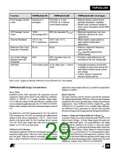
TOPSwitch-FX vs. TOPSwitch-GX
Table 5 compares the features and performance differences
betweenTOPSwitch-GX andTOPSwitch-FX. Manyofthenew
features eliminate the need for additional discrete components.
Other features increase the robustness of design allowing cost
savings in the transformer and other power components.
Function
TOPSwitch-FX
TOPSwitch-GX
TOPSwitch-GX Advantages
Light Load Operation
Cycle skipping
Frequency and Duty Cycle • Improves light load efficiency
reduction
• Reduces no-load consumption
Line Sensing/Externally Line sensing and
Line sensing and externally • Additional design flexibility allows all
Set Current Limit
(Y and R Packages)
externally set
current limit
mutually
set current limit possible
simultaneously
(functions split onto
L and X pins)
features to be used simultaneously
exclusive (M pin)
Current Limit
Programming
Range
100-40%
100-30%
• Minimizes transformer core size
in highly continuous designs
Table 5. Comparison Between TOPSwitch-FX and TOPSwitch-GX. (continued on next page)
E
7/01
August 8, 2000
28

 POWERINT [ Power Integrations ]