TOP242-249
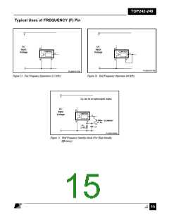
Typical Uses of MULTI-FUNCTION (M) Pin
+
+
VUV = IUV x RLS
VOV = IOV x RLS
C
D
S
S
S
M
S
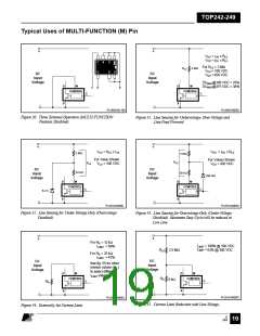
For RLS = 2 MΩ
VUV = 100 VDC
VOV = 450 VDC
RLS
2 MΩ
DC
Input
DC
Input
Voltage
Voltage
DCMAX@100 VDC = 78%
DCMAX@375 VDC = 38%
D
S
M
D
S
M
C
D
S
CONTROL
CONTROL
C
C
-
-
PI-2508-081199
PI-2509-040501
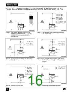
Figure 30. Three Terminal Operation (MULTI-FUNCTION
Features Disabled).
Figure 31. Line Sensing for Undervoltage, Over-Voltage and
Line Feed Forward.
+
+
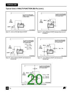
VUV = RLS x IUV
VOV = IOV x RLS
2 MΩ
22 kΩ
2 MΩ
For Value Shown
VUV = 100 VDC
For Values Shown
VOV = 450 VDC
RLS
RLS
DC
Input
Voltage
DC
Input
Voltage
30 kΩ
1N4148
D
S
M
D
S
M
CONTROL
CONTROL
C
C
6.2 V
-
-
PI-2510-040501
PI-2516-040501
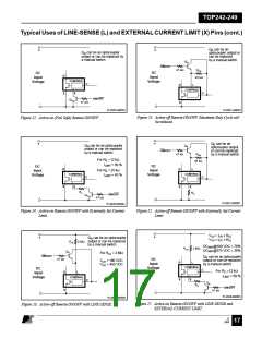
Figure 32. Line Sensing for Under-Voltage Only (Overvoltage
Disabled).
Figure 33. Line Sensing for Overvoltage Only (Under-Voltage
Disabled). Maximum Duty Cycle will be reduced at
Low Line.
+
+
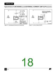
For RIL = 12 kΩ
ILIMIT = 100% @ 100 VDC
ILIMIT = 69%
ILIMIT
=
RLS 2.5 MΩ
63% @ 300 VDC
For RIL = 25 kΩ
ILIMIT = 43%
DC
Input
Voltage
DC
See fig. 55 for other
Input
resistor values (RIL)
Voltage
to select different
D
S
M
D
M
I
LIMIT values
CONTROL
CONTROL
RIL
6 kΩ
C
C
RIL
S
-
-
PI-2518-040501
PI-2517-040501
Figure 35. Current Limit Reduction with Line Voltage.
Figure 34. Externally Set Current Limit.
E
7/01
August 8, 2000
19

 POWERINT [ Power Integrations ]