TOP242-250
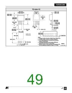
TO-220-7C
.165 (4.19)
.185 (4.70)
.390 (9.91)
.420 (10.67)
.045 (1.14)
.055 (1.40)
.146 (3.71)
.156 (3.96)
.108 (2.74) REF
.234 (5.94)
.261 (6.63)
+
.570 (14.48)
REF.
.461 (11.71)
.495 (12.57)
7° TYP.
.670 (17.02)
REF.
.860 (21.84)
.880 (22.35)
.080 (2.03)
.120 (3.05)
.068 (1.73) MIN
.024 (.61)
PIN 1 & 7
PIN 2 & 4
.040 (1.02)
.060 (1.52)
PIN 1
.010 (.25) M
.034 (.86)
.012 (.30)
.024 (.61)
.040 (1.02)
.060 (1.52)
.050 (1.27) BSC
.150 (3.81) BSC
.190 (4.83)
.210 (5.33)
.050 (1.27)
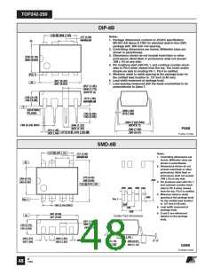
Notes:
.050 (1.27)
1. Controlling dimensions are inches. Millimeter
dimensions are shown in parentheses.
2. Pin numbers start with Pin 1, and continue from left
to right when viewed from the front.
3. Dimensions do not include mold flash or other
protrusions. Mold flash or protrusions shall not
exceed .006 (.15mm) on any side.
.050 (1.27)
.050 (1.27)
.180 (4.58)
.200 (5.08)
4. Minimum metal to metal spacing at the package
body for omitted pin locations is .068 in. (1.73 mm).
5. Position of terminals to be measured at a location
.25 (6.35) below the package body.
.100 (2.54)
PIN 1
PIN 7
.150 (3.81)
.150 (3.81)
6. All terminals are solder plated.
MOUNTING HOLE PATTERN
Y07C
PI-2644-122004
M
12/04
47

 POWERINT [ Power Integrations ]