TOP242-250
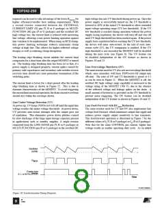
M Pin
X Pin
L Pin
IREM(N)
IUV
IOV
(Enabled)
Output
MOSFET
Switching
(Disabled)
Disabled when supply
output goes out of
regulation
I
ILIMIT (Default)
Current
Limit
I
DCMAX (78.5%)
Maximum
Duty Cycle
I
-22 µA
-27 µA
VBG + VTP
VBG
Pin Voltage
I
-250
-200
-150
-100
-50
0
50
100
150
200
250
300
350
400
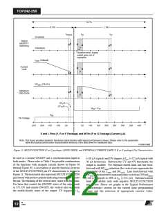
X and L Pins (Y, R or F Package) and M Pin (P or G Package) Current (µA)
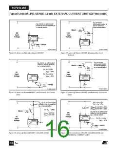
Note: This figure provides idealized functional characteristics with typical performance values. Please refer to the parametric
table and typical performance characteristics sections of the data sheet for measured data.
PI-2636-010802
Figure 11. MULTI-FUNCTION (P or G package), LINSE-SENSE, and EXTERNAL CURRENT LIMIT (Y, R or F package) Pin Characteristics.
be used as a remote ON/OFF and a synchronization input in
both modes. Please refer to Table 3 for possible combinations
(+50 µA typical) and OV triggers at IOV (+225 µA typical with
30 µA hysteresis). Between the UV and OV thresholds, the
of the functions with example circuits shown in Figure 30
through Figure 40. Adescription of specific functions in terms
of the MULTI-FUNCTION pin I/V characteristic is shown in
Figure 11. The horizontal axis representsMULTI-FUNCTION
pincurrentwithpositivepolarityindicatingcurrentsflowinginto
the pin. The meaning of the vertical axes varies with functions.
For those that control the ON/OFF states of the output such
as UV, OV and remote ON/OFF, the vertical axis represents
the enable/disable states of the output. UV triggers at IUV
output is enabled. For external current limit and line feed-
forward with DCMAX reduction, the vertical axis represents the
magnitude of the ILIMIT and DCMAX. Line feed-forward with
DCMAX reductionlowersmaximumdutycyclefrom78%atIM(DC)
(+60 µA typical) to 38% at IOV (+225 µA). External current
limit is available only with negative MULTI-FUNCTION
pin current. Please see graphs in the Typical Performance
Characteristics section for the current limit programming
range and the selection of appropriate resistor value.
M
12 12/04

 POWERINT [ Power Integrations ]