TOP242-250
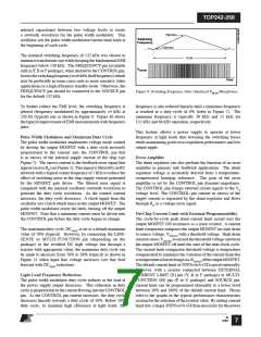
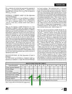
DCMAX reduction, the vertical axis represents the magnitude of
the DCMAX. Line feed-forward with DCMAX reduction lowers
maximum duty cycle from 78% at IL(DC) (+60 µA typical) to
38% at IOV (+225 µA).
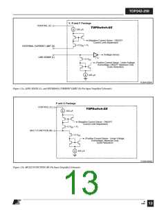
for P and G packages. The comparator with a 1 V threshold
at the LINE-SENSE pin is removed in this case as shown in
Figure 2b. All of the other functions are kept intact. However,
since some of the functions require opposite polarity of input
current(MULTI-FUNCTIONpin),theyaremutuallyexclusive.
Forexample,linesensingfeaturescannotbeusedsimultaneously
with external current limit setting. When current is fed into
the MULTI-FUNCTION pin, it works as a voltage source of
approximately 2.6 V up to a maximum current of +400 µA
(typical). At +400 µA, this pin turns into a constant current
sink. When current is drawn out of the MULTI-FUNCTION
pin, it works as a voltage source of approximately 1.3 V up to
a maximum current of -240 µA (typical). At -240 µA, it turns
into a constant current source. Refer to Figure 12b.
EXTERNAL CURRENT LIMIT (X) Pin Operation
(Y, R and F Packages)
When current is drawn out of the EXTERNAL CURRENT
LIMIT pin, it works as a voltage source of approximately
1.3 V up to a maximum current of -240 µA (typical). At
-240 µA, it turns into a constant current source (refer to
Figure 12a).
There are two functions available through the use of the
EXTERNAL CURRENT LIMIT pin: external current limit
and remote ON/OFF. Connecting the EXTERNALCURRENT
LIMIT pin and SOURCE pin disables the two functions. In
high efficiency applications, this pin can be used to reduce the
current limit externally to a value close to the operating peak
current by connecting the pin to the SOURCE pin through
a resistor. The pin can also be used for remote ON/OFF.
Table2showsseveralpossiblecombinationsusingthispin. See
Figure11foradescriptionofthefunctionswherethehorizontal
axis (left hand side) represents the EXTERNAL CURRENT
LIMIT pin current. The meaning of the vertical axes varies
with function. For those that control the ON/OFF states of the
output such as remote ON/OFF, the vertical axis represents the
enable/disable states of the output. For external current limit,
the vertical axis represents the magnitude of the ILIMIT. Please
see graphs in the Typical Performance Characteristics section
for the current limit programming range and the selection of
appropriate resistor value.
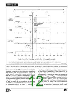
There are a total of five functions available through the use
of the MULTI-FUNCTION pin: OV, UV, line feed-forward
with DCMAX reduction, external current limit and remote
ON/OFF. A short circuit between the MULTI-FUNCTION
pin and SOURCE pin disables all five functions and forces
TOPSwitch-GX to operate in a simple three terminal mode
like TOPSwitch-II. The MULTI-FUNCTION pin is typically
used for line sensing by connecting a resistor from this pin to
the rectified DC high voltage bus to implement OV, UV and
DCMAX reduction with line voltage. In this mode, the value
of the resistor determines the line OV/UV thresholds, and the
DCMAX is reduced linearly with increasing rectified DC high
voltage starting from just above the UV threshold. External
current limit programming is implemented by connecting the
MULTI-FUNCTIONpintotheSOURCEpinthrougharesistor.
However, this function is not necessary in most applications
since the internal current limit of the P and G package devices
has been reduced, compared to the Y, R and F package
devices, to match the thermal dissipation capability of the P
and G packages. It is therefore recommended that the MULTI-
FUNCTION pin is used for line sensing as described above and
not for external current limit reduction. The same pin can also
MULTI-FUNCTION (M) Pin Operation (P and G
Packages)
The LINE-SENSE and EXTERNAL CURRENT LIMIT pin
functions are combined to a single MULTI-FUNCTION pin
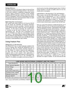
MULTI-FUNCTION PIN TABLE*
Figure Number
Three Terminal Operation
Under-Voltage
30
31
32
33
34
35
36
37
38
39
40
✓
✓
✓
✓
✓
✓
✓
✓
Overvoltage
✓
Line Feed-Forward (DCMAX
Overload Power Limiting
External Current Limit
Remote ON/OFF
)
✓
✓
✓
✓
✓
✓
✓
✓
✓
✓
*This table is only a partial list of many LINE-SENSE and EXTERNAL CURRENT LIMIT pin configurations that are possible.
Table 3. Typcial MULTI-FUNCTION Pin Configurations.
M
12/04
11

 POWERINT [ Power Integrations ]