TOP242-250
Bandgap Reference
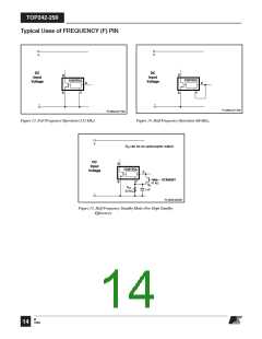
may be used to lower the switching frequency from 132 kHz in
normal operation to 66 kHz in standby mode for very low
standby power consumption.
All critical TOPSwitch-GX internal voltages are derived from
a temperature-compensated bandgap reference. This reference
is also used to generate a temperature-compensated current
reference, which is trimmed to accurately set the switching
frequency, MOSFET gate drive current, current limit, and the
lineOV/UVthresholds. TOPSwitch-GXhasimprovedcircuitry
to maintain all of the above critical parameters within very tight
absolute and temperature tolerances.
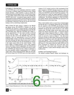
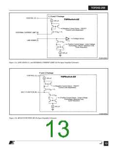
LINE-SENSE (L) Pin Operation (Y, R and F Packages)
When current is fed into the LINE-SENSE pin, it works as
a voltage source of approximately 2.6 V up to a maximum
current of +400 µA (typical). At +400 µA, this pin turns into
a constant current sink. Refer to Figure 12a. In addition, a
comparator with a threshold of 1 V is connected at the pin and
is used to detect when the pin is shorted to the SOURCE pin.
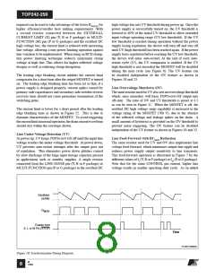
High-Voltage Bias Current Source
This current source biases TOPSwitch-GX from the DRAIN
pin and charges the CONTROL pin external capacitance
during start-up or hysteretic operation. Hysteretic operation
occurs during auto-restart, remote OFF and over-temperature
shutdown. In this mode of operation, the current source
is switched on and off with an effective duty cycle of
approximately 35%. This duty cycle is determined by the
ratio of CONTROL pin charge (IC) and discharge currents
(ICD1 and ICD2). This current source is turned off during normal
operation when the output MOSFET is switching. The effect of
thecurrentsourceswitchingwillbeseenontheDRAINvoltage
waveform as small disturbances and is normal.
There are a total of four functions available through the use of
the LINE-SENSE pin: OV, UV, line feed-forward with DCMAX
reduction, and remote ON/OFF. Connecting the LINE-SENSE
pin to the SOURCE pin disables all four functions. The LINE-
SENSE pin is typically used for line sensing by connecting a
resistor from this pin to the rectified DC high voltage bus to
implement OV, UV and DCMAX reduction with line voltage. In
this mode, the value of the resistor determines the line OV/UV
thresholds, and the DCMAX is reduced linearly with rectified DC
high voltage starting from just above the UVthreshold. The pin
can also be used as a remote ON/OFF and a synchronization
input. RefertoTable2forpossiblecombinationsofthefunctions
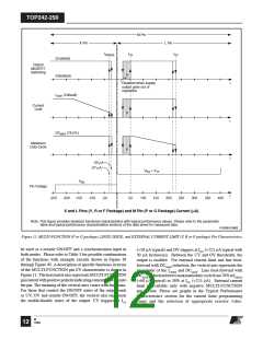
with example circuits shown in Figure 16 through Figure 40. A
description of specific functions in terms of the LINE-SENSE
pin I/V characteristic is shown in Figure 11 (right hand side).
The horizontal axis represents LINE-SENSE pin current with
positive polarity indicating currents flowing into the pin. The
meaning of the vertical axes varies with functions. For those
that control the ON/OFF states of the output such as UV, OV
and remote ON/OFF, the vertical axis represents the enable/
disable states of the output. UV triggers at IUV (+50 µAtypical
with 30 µA hysteresis) and OV triggers at IOV (+225 µA
typical with 8 µA hysteresis). Between the UV and OV
thresholds, the output is enabled. For line feed-forward with
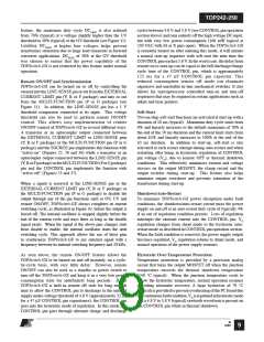
Using Feature Pins
FREQUENCY (F) Pin Operation
The FREQUENCY pin is a digital input pin available in the
Y, R or F package only. Shorting the FREQUENCY pin to
SOURCE pin selects the nominal switching frequency of
132 kHz (Figure 13), which is suited for most applications.
For other cases that may benefit from lower switching
frequency such as noise sensitive video applications, a
66kHzswitchingfrequency(halffrequency)canbeselectedby
shorting the FREQUENCY pin to the CONTROL pin
(Figure 14). In addition, an example circuit shown in Figure 15
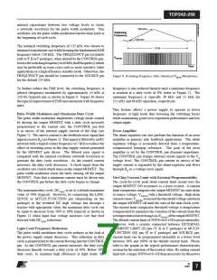
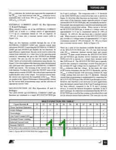
LINE-SENSE AND EXTERNAL CURRENT LIMIT PIN TABLE*
Figure Number
Three Terminal Operation
Under-Voltage
16
17
18
19
20
21
22
23
24
25
26
27
28
29
✓
✓
✓
✓
✓
✓
✓
✓
✓
✓
✓
✓
✓
✓
Overvoltage
✓
Line Feed-Forward (DCMAX
Overload Power Limiting
External Current Limit
Remote ON/OFF
)
✓
✓
✓
✓
✓
✓
✓
✓
✓
✓
✓
✓
✓
✓
*This table is only a partial list of many LINE-SENSE and EXTERNAL CURRENT LIMIT pin configurations that are possible.
Table 2. Typical LINE-SENSE and EXTERNAL CURRENT LIMIT Pin Configurations.
M
10 12/04

 POWERINT [ Power Integrations ]