S/UNI-IMA-4 Telecom Standard Product Data Sheet
Released
Pin/Enable
Unconnected
Unconnected
Unconnected
Unconnected
Unconnected
Unconnected
Unconnected
Unconnected
Cell Type
OUT_CELL
ENABLE
OUT_CELL
ENABLE
OUT_CELL
ENABLE
OUT_CELL
ENABLE
Register Bit
429
430
431
432
433
434
435
436
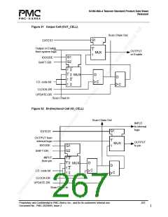
12.1.1 Boundary Scan Cells
In the following diagrams, CLOCK-DR is equal to TCK when the current controller state is
SHIFT-DR or CAPTURE-DR, and unchanging otherwise. The multiplexer in the center of the
diagram selects one of four inputs, depending on the status of select lines G1 and G2. The ID
Code bit is as listed in the Boundary Scan Register table located above.
Figure 30 Input Observation Cell (IN_CELL)
IDCODE
Scan Chain Out
INPUT
Input
to internal
Pad
logic
G1
G2
SHIFT-DR
1 2
1 2
1 2
1 2
D
MUX
C
I.D. Code bit
CLOCK-DR
Scan Chain In
Proprietary and Confidential to PMC-Sierra, Inc., and for its customers’ internal use.
Document No.: PMC-2020889, Issue 2
266

 PMC [ PMC-SIERRA, INC ]