S/UNI®-JET Data Sheet
Released
18 A.C. Timing Characteristics
(T = -40°C to +85°C, V
= 3.3V ±10%)
A
DD
Table 50 RSTB Timing (Figure 77)
Symbol
Description
Min
Typical
100
Max
Units
ns
tV
4
RSTB Pulse Width
RSTB
Figure 77 RSTB Timing
tV
RSTB
RSTB
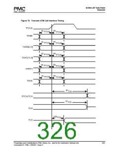
Table 51 Transmit ATM Cell Interface Timing (Figure 78)
Symbol
Description
TFCLK Frequency
Min
Max
52
Units
MHz
f
TFCLK
D
TFCLK Duty Cycle
40
3
60
%
TFCLK
tS
TENB, TADR[2:0], TDATI[15:0], TPRTY, and
TSOC Set-up time to TFCLK
ns
TFCLK
tH
TENB, TADR[2:0], TDATI[15:0], TPRTY, and
1
ns
TFCLK
TSOC Hold time to TFCLK
tP
TFCLK High to DTCA and TCA Valid
TFCLK High to TCA Tri-state
TFCLK High to TCA Driven
1
1
1
12
10
ns
ns
ns
TCA
tZ
TCA
tZB
TCA
Proprietary and Confidential to PMC-Sierra, Inc., and for its Customers’ Internal Use
Document ID: PMC-1990267, Issue 3
325

 PMC [ PMC-SIERRA, INC ]