S/UNI®-8x155 ASSP Telecom Standard Product Data Sheet
Released
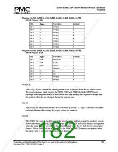
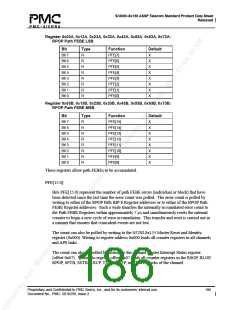
Register 0x035, 0x135, 0x235, 0x335, 0x435, 0x535, 0x635, 0x735:
RPOP Pointer LSB
Bit
Type
Function
PTR[7]
PTR[6]
PTR[5]
PTR[4]
PTR[3]
PTR[2]
PTR[1]
PTR[0]
Default
Bit 7
Bit 6
Bit 5
Bit 4
Bit 3
Bit 2
Bit 1
Bit 0
R
R
R
R
R
R
R
R
X
X
X
X
X
X
X
X
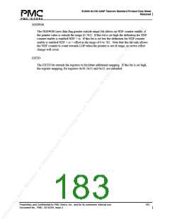
Register 0x036, 0x136, 0x236, 0x336, 0x436, 0x536, 0x636, 0x736:
RPOP Pointer MSB
Bit
Type
R/W
R/W
R/W
Function
NDFPOR
EXTD
RDI10
Unused
S1
S0
PTR[9]
PTR[8]
Default
0
0
0
X
X
X
X
X
Bit 7
Bit 6
Bit 5
Bit 4
Bit 3
Bit 2
Bit 1
Bit 0
R
R
R
R
PTR[9:0]:
The PTR[7:0] bits contain the current pointer value as derived from the H1 and H2 bytes.
To ensure reading a valid pointer, the NDFI, NSEI and PSEI bits of the RPOP Pointer
Interrupt Status register should be read before and after reading this register to ensure that
the pointer value did not changed during the register read.
S0, S1:
The S0 and S1 bits contain the two S bits received in the last H1 byte. These bits should be
software debounced to ensure the proper values are received.
RDI10:
The RDI10 bit controls the filtering of the remote defect indication and the auxiliary remote
defect indication. When RDI10 is set to logic one, the PRDI and ARDI statuses are updated
when the same value is received in the corresponding bit of the G1 byte for 10 consecutive
frames. When PRDI10 is set to logic zero, the PRDI and ARDI statuses are updated when
the same value is received for 5 consecutive frames.
Proprietary and Confidential to PMC-Sierra, Inc., and for its customers’ internal use.
Document No.: PMC- 2010299, Issue 2
182

 PMC [ PMC-SIERRA, INC ]