Z0103/07/09 series
Philips Semiconductors
Triacs
5. Thermal characteristics
Table 4:
Symbol
Rth(j-sp)
Thermal characteristics
Parameter
Conditions
Min Typ Max Unit
thermal resistance from junction to solder
point for SOT223
-
-
25
K/W
Figure 5
Rth(j-lead)
Rth(j-a)
thermal resistance from junction to lead for
SOT54B (TO-92)
-
-
60
K/W
Figure 5
thermal resistance from junction to ambient
SOT223
minimum footprint; mounted on a PCB
vertical in free air
-
-
60
-
K/W
K/W
SOT54B (TO-92)
150 -
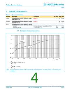
5.1 Transient thermal impedance
003aaa206
10
a
1
SOT223
-1
10
SOT54B
-2
10
-3
-4
10
10
-5
-4
-3
-2
-1
2
3
10
10
10
10
10
1
10
10
10
t
(s)
p
Zth( j – lead)
a =
for SOT54B (TO-92)
---------------------------
Rth( j – lead)
Zth( j – sp)
a =
for SOT223
----------------------
Rth( j – sp)
Fig 5. Transient thermal impedance from junction to lead and junction to solder point as a function of pulse
duration.
9397 750 10102
© Koninklijke Philips Electronics N.V. 2002. All rights reserved.
Product data
Rev. 02 — 12 September 2002
4 of 12

 NXP [ NXP ]