Philips Semiconductors
Preliminary specification
Stereo audio codec with SPDIF interface
UDA1355H
SYMBOL
PARAMETER
data hold time
CONDITIONS
MIN.
TYP. MAX. UNIT
tHD;DAT
tSP
0
0
−
−
−
−
−
µs
ns
pF
pulse width of spikes
load capacitance
note 5
for each bus line
50
400
CL
Notes
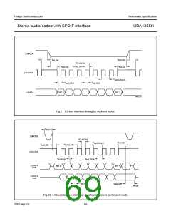
1. In order to prevent digital noise interfering with the L3-bus communication, the rise and fall times should be as small
as possible.
2. When the sampling frequency is below 32 kHz, the L3CLOCK cycle must be limited to 1⁄64fs cycle.
3. Cb is the total capacitance of one bus line in pF. The maximum capacitive load for each bus line is 400 pF.
4. After this period, the first clock pulse is generated.
5. To be suppressed by the input filter.
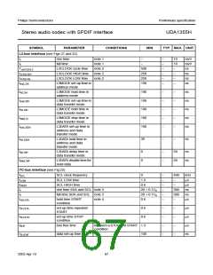
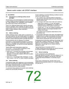
handbook, full pagewidth
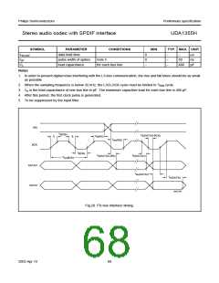
WS
t
BCKH
t
d(DATAO-BCK)
t
t
t
f
h(WS)
r
t
su(WS)
BCK
t
BCKL
t
t
h(DATAO)
d(DATAO-WS)
T
cy(BCK)
DATAO
DATAI
t
su(DATAI)
t
h(DATAI)
MGS756
Fig.20 I2S-bus interface timing.
2003 Apr 10
68

 NXP [ NXP ]