Philips Semiconductors
Preliminary specification
Economy audio CODEC for MiniDisc (MD)
home stereo and portable applications
UDA1341TS
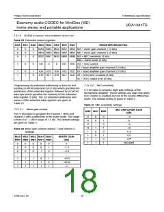
7.21.3 DATA0 EXTENDED PROGRAMMING REGISTERS
Table 25 Extended control registers
EA2 EA1 EA0 ED4 ED3 ED2 ED1 ED0
REGISTER SELECTED
0
0
0
0
0
1
0
1
0
MA4 MA3 MA2 MA1 MA0 MA = mixer gain channel 1 (5 bits)
MB4 MB3 MB2 MB1 MB0 MB = mixer gain channel 2 (5 bits)
MS2 MS1 MS0 MM1 MM0 MS = MIC sensitivity (3 bits)
MM = mixer mode (2 bits)
1
0
0
AG
0
0
IG1 IG0 AG = AGC control
IG = input amplifier gain channel 2 (2 bits)
1
1
0
1
1
0
IG6 IG5 IG4 IG3 IG2 IG = input amplifier gain channel 2 (5 bits)
AT2 AT1 AT0 AL1 AL0 AT = AGC time constant (3 bits)
AL = AGC output level (2 bits)
Programming via extended addressing is done by first
sending a DATA0 data byte EA (3 bits) which specifies the
addresses of the extended register followed by a DATA0
data byte which specifies the contents of the extended
data register (5 bits). The EA extended addresses and
names of the extended data registers are given in
Table 25.
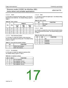
7.21.3.2 MIC sensitivity
A 3-bit value to program eight gain settings of the
microphone amplifier. These settings are valid only when
AGC control is enabled and not in the double differential
mode. The default setting is given in Table 5.
Table 27 MIC sensitivity settings
7.21.3.1 Mixer gain control
MIC AMPLIFIER GAIN
MS2 MS1 MS0
(dB)
Two 5-bit values to program the channel 1 (MA) and
channel 2 (MB) coefficients in the mixer mode. The range
is from 0 to −∞ dB in steps of 1.5 dB. The default settings
are given in Table 5.
0
0
0
0
1
1
1
1
0
0
1
1
0
0
1
1
0
1
0
1
0
1
0
1
−3
0
+3
+9
Table 26 Mixer gain control channel 1 and channel 2
+15
+21
+27
not used
settings
MA4 MA3 MA2 MA1 MA0
MB4 MB3 MB2 MB1 MB0
MIXER GAIN
(dB)
0
0
0
:
0
0
0
:
0
0
0
:
0
0
1
:
0
1
0
:
0
−1.5
−3.0
:
1
1
1
1
1
1
1
1
1
0
1
1
1
0
1
−43.5
−45.0
−∞
1998 Dec 18
18

 NXP [ NXP ]