Philips Semiconductors
Preliminary specification
Economy audio CODEC for MiniDisc (MD)
home stereo and portable applications
UDA1341TS
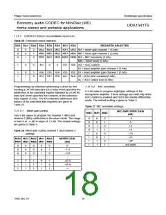
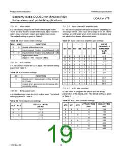
7.21.3.3 Mixer mode
7.21.3.6 Input channel 2 amplifier gain
A 2-bit value to program the mode of the digital mixer.
There are four modes: double differential, input channel 1
select, input channel 2 select and digital mixer mode.
The default setting is given in Table 5.
A 7-bit value to program the input channel 2 amplifier gain.
The range is from −3 to +60.5 dB in steps of 0.5 dB. These
settings are only valid when AGC control is disabled and
not valid in the double differential mode.
Table 28 Mixer mode switch settings
Table 31 Input channel 2 amplifier gain settings
MM1 MM0
FUNCTION
double differential mode
INPUT
CHANNEL 2
AMPLIFIER
GAIN
0
0
1
1
0
1
0
1
IG6 IG5 IG4 IG3 IG2 IG1 IG0
input channel 1 select (input channel 2 off)
input channel 2 select (input channel 1 off)
(dB)
digital mixer mode
(input 1 × MA + input 2 × MB)
0
0
0
0
0
0
0
:
0
0
0
0
0
0
0
:
0
0
0
0
0
0
0
:
0
0
0
0
0
0
0
:
0
0
0
0
1
1
1
:
0
0
1
1
0
0
1
:
0
1
0
1
0
1
0
:
−3.0
−2.5
−2.0
−1.5
−1.0
−0.5
0.0
7.21.3.4 AGC control
A 1-bit value to enable the AGC input. The default setting
is given in Table 5.
Table 29 AGC control settings
:
AG
FUNCTION
1
1
1
1
1
1
1
1
1
1
1
1
1
1
1
0
1
1
1
0
1
59.5
60.0
60.5
0
disable AGC: manual gain setting through
IG (7 bits)
1
enable AGC: gain control with manual MIC
sensitivity setting
7.21.3.7 AGC time constant
7.21.3.5 AGC output level
A 3-bit value to program the attack and the decay
parameters of the digital AGC. The default setting is given
in Table 5.
A 2-bit value to program the AGC output level. The default
setting is given in Table 5.
Table 32 AGC time constant settings
Table 30 AGC output level settings
ATTACK TIME
(ms)
DECAY TIME
(ns)
OUTPUT LEVEL
AT2 AT1 AT0
AL1 AL0
(dB FS)
0
0
0
0
1
1
1
1
0
0
1
1
0
0
1
1
0
1
0
1
0
1
0
1
11
16
11
16
21
11
16
21
100
100
200
200
200
400
400
400
0
0
1
1
0
1
0
1
−9.0
−11.5
−15.0
−17.5
1998 Dec 18
19

 NXP [ NXP ]