Philips Semiconductors
Product specification
New In Car Entertainment car radio tuner IC with
Precision Adjacent Channel Suppression (NICE-PACS)
TEA6848H
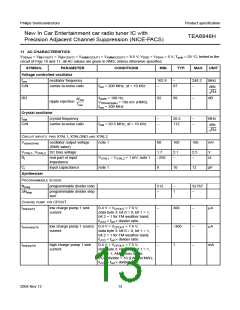
11 AC CHARACTERISTICS
VDDA(n) = VMIX1OUT1 = VMIX1OUT2 = VAMMIX2OUT1 = VAMMIX2OUT2 = 8.5 V; VDDD = VDDA5 = 5 V; Tamb = 25 °C; tested in the
circuit of Figs 10 and 11; all AC values are given in RMS; unless otherwise specified.
SYMBOL
PARAMETER
CONDITIONS
MIN.
TYP.
MAX. UNIT
Voltage controlled oscillator
fosc
oscillator frequency
162.9
−
248.2
MHz
C/N
carrier-to-noise ratio
f
osc = 200 MHz; ∆f = 10 kHz
−
97
−
dBc
-----------
Hz
RR
fripple = 100 Hz;
VDDA4(ripple) = 100 mV (RMS);
fosc = 200 MHz
92
99
−
dB
∆fosc
ripple rejection
-----------
fosc
Crystal oscillator
fxtal
crystal frequency
−
−
20.5
112
−
−
MHz
C/N
carrier-to-noise ratio
fxtal = 20.5 MHz; ∆f = 10 kHz
dBc
-----------
Hz
CIRCUIT INPUTS: PINS XTAL1, XTALGND AND XTAL2
Vo(osc)(rms)
oscillator output voltage
(RMS value)
note 1
80
100
160
mV
VXTAL1, VXTAL2 DC bias voltage
1.7
2.1
2.5
V
Ri
real part of input
impedance
V
XTAL1 − VXTAL2 = 1 mV; note 1
−250
−
−
Ω
Ci
input capacitance
note 1
8
10
12
pF
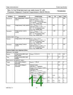
Synthesizer
PROGRAMMABLE DIVIDER
Nprog
programmable divider ratio
512
−
32767
∆Nstep
programmable divider step
size
−
1
−
CHARGE PUMP: PIN CPOUT
Isink(cp1)l
low charge pump 1 sink
current
0.4 V < VCPOUT < 7.6 V;
−
−
−
300
−300
1
−
−
−
µA
µA
mA
data byte 3: bit 0 = 0, bit 1 = 1,
bit 2 = 1 for FM weather band;
fVCO > fref × divider ratio
Isource(cp1)l
low charge pump 1 source 0.4 V < VCPOUT < 7.6 V;
current
data byte 3: bit 0 = 0, bit 1 = 1,
bit 2 = 1 for FM weather band;
fVCO < fref × divider ratio
Isink(cp1)h
high charge pump 1 sink
current
0.4 V < VCPOUT < 7.6 V;
data byte 3: bit 0 = 1, bit 1 = 1,
bit 2 = 1; AM stereo mode;
VCO divider = 10 (LW and MW);
fVCO > fref × divider ratio
2004 Nov 12
13

 NXP [ NXP ]