Philips Semiconductors
Preliminary specification
Sound fader control circuit
TEA6320
Loudness filter calculation example
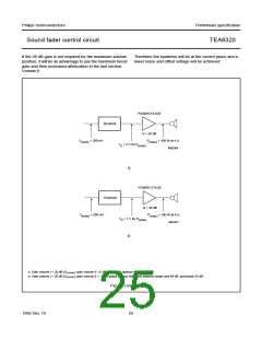
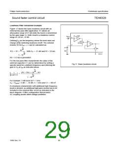
Figure 17 shows the basic loudness circuit with an
external low-pass filter application. R1 allows an
attenuation range of 21 dB while the boost is determined
by the gain stage V2. Both result in a loudness control
range of +20 to −12 dB.
handbook, halfpage
0 dB
C
KVL
8
9
V
1
Defining fref as the frequency where the level does not
change while switching loudness on/off. The external
resistor R3 for fref → ∞ can be calculated as:
R1
33 kΩ
V
2
Gv
------
C1
R3
R2
1020
R3 = R1
. With G = −21 dB and R1 = 33 kΩ,
v
---------------------
Gv
------
MED437
1 – 1020
R3 = 3.2 kΩ is generated.
For the low-pass filter characteristic the value of the
external capacitor C1 can be determined by setting a
specific boost for a defined frequency and referring the
gain to Gv at fref as indicated above.
Fig.17 Basic loudness circuit.
Gv
------
(R1 + R3) × 1020 – R3
1
=
-------------------------------------------------------------
--------------------
Gv
j (ω C1)
------
1 – 1020
For example: 3 dB boost at f = 1 kHz
Gv = Gv(ref) + 3 dB = −18 dB; f = 1 kHz and C1 = 100 nF.
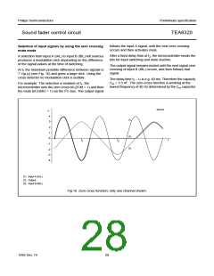
If a loudness characteristic with additional high frequency
boost is desired, an additional high-pass section has to be
included in the external filter circuit as indicated in the
block diagram. A filter configuration that provides
AC coupling avoids offset voltage problems.
1995 Dec 19
29

 NXP [ NXP ]