Philips Semiconductors
Product specification
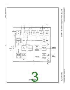
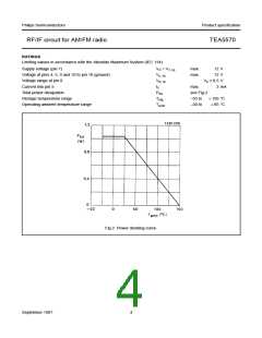
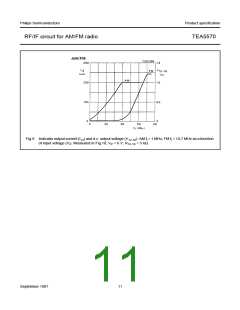
RF/IF circuit for AM/FM radio
TEA5570
PARAMETER
Indicator/level detector (pin 12)
Indicator current
SYMBOL
MIN.
TYP.
MAX.
UNIT
I
−
250
325
µA
12
D.C. output voltage
at V = 300 µV
V
−
−
0,25
1,0
−
−
V
V
i
12-16
at V = 2 mV
V
i
12-16
AM to FM switch
Switching current at V
< 1 V
−I
−
−
400
µA
3-16
3
Notes to the characteristics
1. Oscillator operates at V
> 2,25 V.
7-16
Vi1
2. I.F. suppression is defined as the ratio α = 20 log
where: V is the input voltage at f = 455 kHz and V is the
-------
Vi2
i1
i2
input voltage at f = 1 MHz.
3. Oscillator voltage at pin 8 can be preset by R (see Fig.10).
osc
V 3 – 16
4. Maximum current into pin 5 can be adjusted by R1 (see Fig.10); I =
− I when V
= 800 mv; I = 400 µA.
---------------
R1
5
3
3-16
3
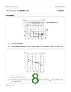
5. AM suppression is measured with f = 1 kHz, m = 0,3 for AM; f = 400 Hz, ∆f = ± 22,5 kHz for FM.
m
m
Facility adaptation
Facility adaptation is achieved as follows (see Fig.10):
FACILITY
COMPONENT
V 3 – 16
FM sensitivity
R1 fixes the current at pin 5 (I =
− 400 µA)
---------------
R1
5
(gain adjustable ± 10 dB; see note 4)
AM sensitivity
R11 and coil tapping
AM oscillator biasing
AM output voltage
AM a.g.c. setting
R
osc
R7, R11
R7
September 1987
7

 NXP [ NXP ]