Philips Semiconductors
Product specification
RF/IF circuit for AM/FM radio
TEA5570
A.C. CHARACTERISTICS
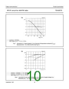
AM performance
V = 6 V; T
= 25 °C; r.f. condition: f = 1 MHz, m = 0,3, f = 1 kHz; transfer impedance of the i.f. filter
i m
P
amb
|Z | = v /I = 2,7 kΩ; measured in Fig.10; unless otherwise specified
tr
6 4
PARAMETER
SYMBOL
MIN.
TYP.
MAX.
UNIT
R.F. sensitivity (pin 2)
at V = 30 mV
V
3,5
5,0
7,0
µV
o
i
at S + N/N = 6 dB
at S + N/N = 26 dB
at S + N/N = 50 dB
V
V
V
V
V
−
1,3
16
1
µV
i
−
20
−
µV
i
−
mV
mV
mV
i
Signal handling (THD ≤ 10% at m = 0,8)
200
80
−
−
i
A.F. output voltage at V = 1 mV
100
125
i
o
Total harmonic distortion
at V = 100 µV to 100 mV (m = 0,3)
THD
THD
THD
α
−
0,5
1,0
4,0
35
−
%
%
%
dB
i
at V = 2 mV (m = 0,8)
−
2,5
10
−
i
at V = 200 mV (m = 0,8)
−
i
I.F. suppression at V = 30 mV (note 2)
26
o
Oscillator voltage (pin 8; note 3)
at f
= 1455 kHz
V
120
160
200
200
230
mV
osc
8-16
Indicator current (pin 12) at V = 1 mV
I
−
µV
i
12
FM performance
V = 6 V; T
= 25 °C; i.f. condition: f = 10,7 MHz, ∆f = ± 22,5 kHz, f = 1 kHz; transfer impedance of the i.f. filter
P
amb
i
m
|Z | = v /i = 275 Ω; measured in Fig.10; unless otherwise specified
tr
6 5
PARAMETER
SYMBOL
MIN.
TYP.
MAX.
UNIT
I.F. part
I.F. sensitivity (adjustable; note 4)
Input voltage
at −3 dB before limiting
at S + N/N = 26 dB
V
90
110
130
µV
i
V
V
V
−
6
−
µV
mV
mV
%
i
at S + N/N = 65 dB
−
1
−
i
A.F. output voltage at V = 1 mV
80
−
100
0,3
50
125
−
i
o
Total harmonic distortion at V = 1 mV
THD
AMS
i
AM suppression (note 5)
−
−
dB
September 1987
6

 NXP [ NXP ]