TDA8944J
2 x 7 W stereo BTL audio amplifier
Philips Semiconductors
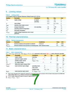
MGL955
MGL954
50
50
handbook, halfpage
handbook, halfpage
I
I
q
q
(mA)
(mA)
40
40
30
20
10
30
20
V
= 12 V
CC
10
0
0
0
4
8
12
16
V
20
(V)
0
4
8
12
16
V
20
(V)
MODE
CC
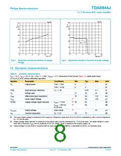
Fig 3. Quiescent current as function of supply
voltage.
Fig 4. Quiescent current as function of mode voltage.
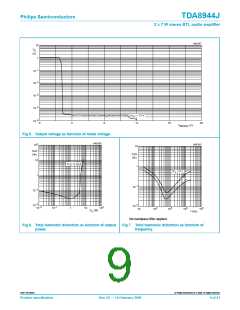
12. Dynamic characteristics
Table 8: Dynamic characteristics
VCC = 12 V; Tamb = 25 °C; RL = 8 Ω; f = 1 kHz; VMODE = 0 V; measured in test circuit Figure 14; audio pass band
22 Hz to 22 kHz; unless otherwise specified.
Symbol
Parameter
Conditions
THD = 10%
THD = 0.5%
Po = 1 W
Min
6
Typ
7
Max
-
Unit
W
Po
output power
4
5
-
W
THD
Gv
total harmonic distortion
voltage gain
-
0.03
32
90
90
65
60
0.1
33
110
120
-
%
31
70
-
dB
kΩ
µV
dB
dB
Zi(dif)
Vn(o)
SVRR
differential input impedance
noise output voltage
[1]
[2]
[2]
supply voltage ripple rejection
fripple = 1 kHz
50
-
fripple = 100 Hz
to 20 kHz
-
[3]
Vo(mute)
output voltage
mute mode
-
-
50
-
µV
αcs
channel separation
Rs = 0 Ω
50
75
dB
[1] The noise output voltage is measured at the output in a frequency range from 20 Hz to 20 kHz (unweighted), with a source impedance
Rs = 0 Ω at the input.
[2] Supply voltage ripple rejection is measured at the output, with a source impedance Rs = 0 Ω at the input. The ripple voltage is a sine
wave with a frequency fripple and an amplitude of 707 mV (RMS), which is applied to the positive supply rail.
[3] Output voltage in mute mode is measured with an input voltage of 1 V (RMS) in a bandwidth of 20 kHz, so including noise.
9397 750 06861
© Philips Electronics N.V. 2000. All rights reserved.
Product specification
Rev. 02 — 14 February 2000
8 of 21

 NXP [ NXP ]