TDA8931
Philips Semiconductors
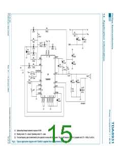
Power comparator 1 × 20 W
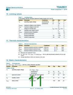
10. Limiting values
Table 7:
Limiting values
In accordance with the Absolute Maximum Rating System (IEC 60134).
Symbol Parameter
Conditions
asymmetrical
symmetrical
Min
12
±6
-
Max
40
Unit
V
VP
operating supply voltage
±20
14
V
VENABLE maximum voltage on pin ENABLE
V
VOVP
Vn
maximum voltage on pin OVP
voltage on all other pins
repetitive peak output current
maximum power dissipation
junction temperature
-
14
V
V
SS − 0.3 VDD + 0.3 V
IORM
Pd(max)
Tj
-
8
A
-
2.5
150
+150
+85
W
°C
°C
°C
-
Tstg
storage temperature
−55
−40
Tamb
ambient temperature
11. Thermal characteristics
Table 8:
Thermal characteristics
Symbol Parameter
Conditions
Typ
24
16
3
Unit
[1]
[2]
[3]
Rth(j-a)
Rth(j-p)
Rth(j-c)
thermal resistance junction to ambient in free air
K/W
K/W
K/W
thermal resistance junction to pin
thermal resistance junction to case
in free air
in free air
[1] Measured in the application board.
[2] Vp = 22 V; RL = 4 Ω; Vripple = 2 V (p-p); fripple = 100 Hz with feed-forward network (470 kΩ and
15 nF).
[3] Strongly depending on where you measure on the case.
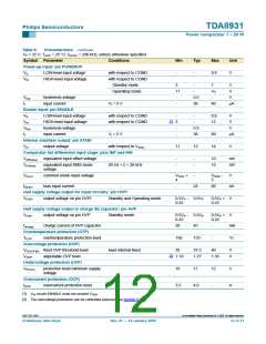
12. Static characteristics
Table 9:
Characteristics
VP = 22 V; Tamb = 25 °C; fcarrier = 290 kHz; unless otherwise specified.
Symbol Parameter
Supply voltage
Conditions
Min
Typ
Max
Unit
VP
operating supply voltage
VP = VDDP − VSSP
asymmetrical
symmetrical
12
±6
-
22
35
V
±11
20
±17.5
30
V
Iq
quiescent current
standby current
sleep current
with load; filter and snubbers
connected
mA
Istb
Isleep
Standby mode; SE capacitor
charged
-
-
10
15
mA
Sleep mode
100
200
µA
9397 750 13847
© Koninklijke Philips Electronics N.V. 2005. All rights reserved.
Preliminary data sheet
Rev. 01 — 14 January 2004
11 of 31

 NXP [ NXP ]