TDA8920B
Philips Semiconductors
2 × 100 W class-D power amplifier
If two or more class-D amplifiers are used in the same audio application, it is strongly
recommended that all devices run at the same switching frequency. This can be realized
by connecting all OSC pins together and feed them from an external central oscillator.
Using an external oscillator it is necessary to force pin OSC to a DC-level above SGND for
switching from the internal to an external oscillator. In this case the internal oscillator is
disabled and the PWM will be switched on the external frequency. The frequency range of
the external oscillator must be in the range as specified in the switching characteristics;
see Section 12.1.
In an application circuit:
• Internal oscillator: ROSC connected between pin OSC and VSSA
• External oscillator: connect the oscillator signal between pins OSC and SGND; delete
ROSC and COSC
.
13.5 Heatsink requirements
In some applications it may be necessary to connect an external heatsink to the
TDA8920B. Limiting factor is the 150 °C maximum junction temperature Tj(max) which
cannot be exceeded. The expression below shows the relationship between the maximum
allowable power dissipation and the total thermal resistance from junction to ambient:
T j(max) – Tamb
Rth( j – a)
=
(5)
-----------------------------------
Pdiss
Pdiss is determined by the efficiency (η) of the TDA8920B. The efficiency measured in the
TDA8920B as a function of output power is given in Figure 21.The power dissipation can
be derived as function of output power (see Figure 20).
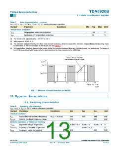
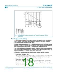
The derating curves (given for several values of the Rth(j-a)) are illustrated in Figure 8.
A maximum junction temperature Tj = 150 °C is taken into account. From Figure 8 the
maximum allowable power dissipation for a given heatsink size can be derived or the
required heatsink size can be determined at a required dissipation level.
9397 750 13356
© Koninklijke Philips Electronics N.V. 2004. All rights reserved.
Preliminary data sheet
Rev. 01 — 1 October 2004
17 of 34

 NXP [ NXP ]