Philips Semiconductors
Product specification
2 × 25 W BTL stereo car radio power amplifier
with differential inputs and diagnostic outputs
TDA8566Q
TEST AND APPLICATION INFORMATION
handbook, full pagewidth
+
+
V
P =
2200
µF/16V
100
nF
V
mode
14.4 V
_
_
14
5
13
1
+
_
+
−
+
_
6
R /2
s
220 nF
220 nF
60
kΩ
TDA8566Q
R
V
L1
in1
60
kΩ
−
+
V
V
P
P
8
4
R /2
s
2
3
10
10
kΩ
kΩ
CLIP
CLIP
V
DETECTOR
ref
+
−
DIAGNOSTIC 15
INTERFACE
DIAG
+ 16
+
−
10 +
R /2
s
220 nF
220 nF
60
kΩ
R
V
L2
in2
60
kΩ
17
−
+
_
12
R /2
s
_
7
11
MGD104
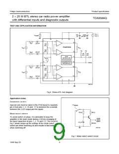
Fig.6 Stereo BTL test diagram.
Application notes
DIAGNOSTIC OUTPUT
+V
Special care must be taken in the PCB layout to separate
pin 4 from pins 1, 2, 16 and 17 to minimize the crosstalk
between the CLIP output and the inputs.
supply
S
handbook, halfpage
10 kΩ
47 µF
100 Ω
MODE SELECT SWITCH
To avoid switch on plops, it is advisable to keep the
amplifier in the mute mode during ≥150 ms (charging of
the input capacitors at pins 1, 2, 16 and 17). The circuit in
Fig.7 slowly ramps-up the voltage at the mode select
switch pin when switching on and results in fast muting
when switching off.
mode
select
switch
100 kΩ
MGD102
Fig.7 Mode select switch circuit.
1998 Sep 23
9

 NXP [ NXP ]