Philips Semiconductors
Product specification
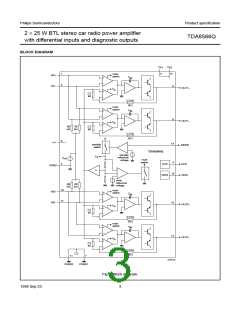
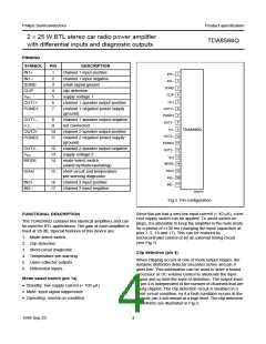
2 × 25 W BTL stereo car radio power amplifier
with differential inputs and diagnostic outputs
TDA8566Q
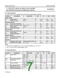
DC CHARACTERISTICS
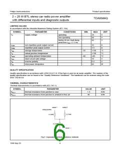
VP = 14.4 V; Tamb = 25 °C; measured in test circuit of Fig.6; unless otherwise specified.
SYMBOL
PARAMETER
CONDITIONS
MIN.
TYP.
MAX.
UNIT
Supply voltage
VP
Iq
supply voltage
quiescent current
note 1
RL =
6
14.4
18
V
−
115
180
mA
Operating condition
Vms(op) mode select switch level
I14
8.5
−
−
VP
40
−
V
mode select switch current
output voltage
V14 = 14.4 V
note 2
15
7.0
−
µA
V
Vo
−
Vos
output offset voltage
−
100
mV
Mute condition
Vms(mute) mode select switch level
Vo
3.3
−
−
6.4
−
V
output voltage
note 2
7.0
−
V
Vos
output offset voltage
−
100
mV
Standby condition
Vms(stb) mode select switch level
Istb
0
−
2
V
standby current
−
0.1
100
µA
Diagnostic
V15
Tvj
diagnostic output voltage
temperature pre-warning
during any fault condition
V15 = 0.6 V
−
−
−
0.6
V
145
−
°C
Notes
1. The circuit is DC adjusted at VP = 6 to 18 V and AC operating at VP = 8.5 to 18 V.
2. At VP = 18 to 30 V the DC output voltage ≤ 0.5VP.
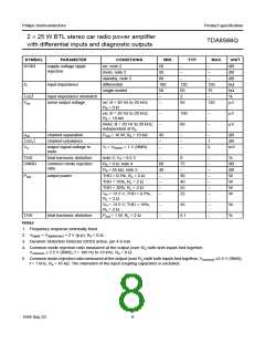
AC CHARACTERISTICS
VP = 14.4 V; Tamb = 25 °C; RL = 4 Ω; fi = 1 kHz; measured in test circuit of Fig.6; unless otherwise specified.
SYMBOL
PARAMETER
output power
CONDITIONS
THD = 0.5%
MIN.
TYP.
MAX.
UNIT
Pout
16
21
28
−
19
25
35
−
−
−
−
−
W
W
W
%
W
THD = 10%
THD = 30%
THD
Pout
total harmonic distortion
output power
Pout = 1 W
0.05
14
−
VP = 13.5 V; THD = 0.5%
VP = 13.5 V; THD = 10%
−
−
22
−
−
W
B
power bandwidth
THD = 0.5%; Pout = −1 dB
20 to 20000
Hz
with respect to 16 W
fl
low frequency roll off
high frequency roll off
closed loop voltage gain
−1 dB, note 1
−1dB
−
25
−
−
−
Hz
fh
Gv
20
25
kHz
dB
26
27
1998 Sep 23
7

 NXP [ NXP ]