Philips Semiconductors
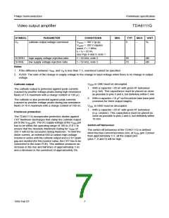
Preliminary specification
Video output amplifier
TDA6111Q
The dynamic dissipation equals:
dyn = VDDH × (CL + Cfb + Cint) × fi × Vo(p-p) × δ
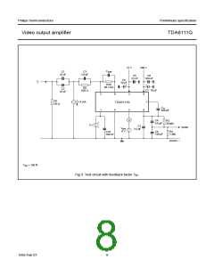
TEST AND APPLICATION INFORMATION
Dissipation
P
CL = load capacitance.
Regarding dissipation, distinction must first be made
between static dissipation (independent of frequency) and
dynamic dissipation (proportional to frequency).
Cfb = feedback capacitance (≈ 150 fF).
Cint = internal load capacitance (≈ 4 pF).
fi = input frequency.
The static dissipation of the TDA6111Q is due to high and
low voltage supply currents and load currents in the
feedback network and CRT.
Vo(p-p) = output voltage (peak-to-peak value).
δ = non-blanking duty-cycle (≈ 0.8).
The static dissipation equals:
With CL = 10 pF, Cfb = 0, Cint = 4 pF, fi = 8 MHz
(simulation of worst-case noise), Vo(p-p) = 100 V and
δ = 80% then Pdyn = 1.8 W
Pstat = VDDL × IDDL + VDDH × IDDH
Vfb
+ Voc × Ioc – Vfb
×
--------
The IC must be mounted on the picture tube base print to
minimize the load capacitance (CL).
Rfb
Rfb = value of feedback resistor.
Ioc = DC value of cathode current.
The total power dissipation, Ptot = Pstat + Pdyn thus
amounts to 3.6 W under given conditions.
From Tj = Tamb + Ptot × Rth j-a < Tj(max) = 150 °C, Rth j-a of
the package and heatsink together must be < 24 K/W.
With Vfb = Voc = 100 V, Rfb = 68 kΩ, Ioc = 0.6 mA and
other typical conditions as mentioned in Chapter
“Characteristics”, the static dissipation Pstat = 2.0 W.
1995 Feb 07
11

 NXP [ NXP ]