Philips Semiconductors
Product specification
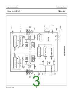
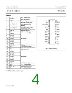
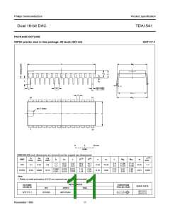
Dual 16-bit DAC
TDA1541
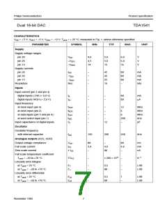
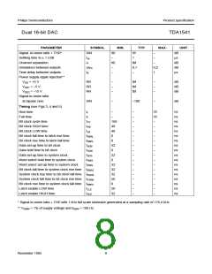
CHARACTERISTICS
VDD = + 5 V; VDD1 = −5 V; VDD2 = −12 V; Tamb = + 25 °C; measured in Fig. 1; unless otherwise specified.
PARAMETER SYMBOL MIN. TYP. MAX.
UNIT
Supply
Supply voltage ranges
pin 28
VDD
4,0
4,5
14
5,0
5,0
15
6,0
6,0
16
V
V
V
pin 26
−VDD1
−VDD2
pin 15
Supply currents
pin 28
IDD
−
−
−
−
45
45
25
16
tbf
tbf
tbf
−
mA
mA
mA
bits
pin 26
−IDDI
−IDD2
Res
pin 15
Resolution
Inputs
Input current (pin 3 and pin 4)
digital inputs LOW (< 0,8 V)
digital inputs HIGH (> 2,0 V)
Input frequency
IIL
−
−
−
−
tbf
tbf
mA
IIH
µA
at clock input (pin 4)
fSCK
fBCK
fDAT
fWS
CI
−
−
−
−
−
−
12
6
MHz
MHz
MHz
kHz
pF
at clock input (pin 2)
−
at data inputs (pin 3 and pin 4)
at word select input (pin 1)
Input capacitance of digital inputs
−
6
−
200
12
−
Oscillator
Oscillator frequency
with internal capacitor
fosc
150
200
250
kHz
Analogue outputs (AOL; AOR)
Output voltage compliance
Full scale current
VOC
IFS
tbf
3,4
−
−
tbf
4,6
−
mV
mA
nA
4,0
tbf
Zero scale current
± IZS
Full scale temperature coefficient
Tamb = −20 to +70 °C
Linearity error integral
at Tamb = 25 °C
TCFS
−
± 200 × 10-6
−
K−1
E1
E1
−
−
0,5
tbf
−
−
LSB
LSB
at Tamb = −20 to +70 °C
Linearity error differential
at Tamb = 25 °C
Ed1
Ed1
−
−
0,5
tbf
1
LSB
LSB
at Tamb = −20 to +70 °C
−
November 1985
7

 NXP [ NXP ]