PMBT3906
NXP Semiconductors
PNP switching transistor
6. Thermal characteristics
Table 6.
Thermal characteristics
Symbol Parameter
Conditions
Min
Typ
Max
Unit
[1]
Rth(j-a)
thermal resistance from
junction to ambient
in free air
-
-
500
K/W
[1] Device mounted on an FR4 PCB.
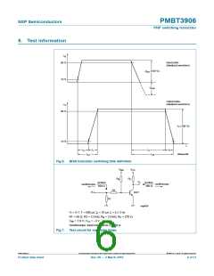
7. Characteristics
Table 7.
Characteristics
Tamb = 25 °C unless otherwise specified.
Symbol Parameter Conditions
Min
Typ
Max
Unit
ICBO
IEBO
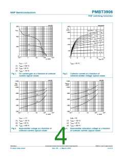
hFE
collector-base cut-off VCB = −30 V; IE = 0 A
current
-
-
−50
nA
emitter-base cut-off VEB = −6 V; IC = 0 A
current
-
-
−50
nA
DC current gain
VCE = −1 V
IC = −0.1 mA
60
-
-
-
-
-
-
-
-
-
-
-
-
-
-
-
-
-
IC = −1 mA
80
-
IC = −10 mA
100
300
-
IC = −50 mA
60
IC = −100 mA
30
-
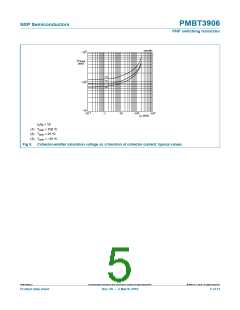
VCEsat
collector-emitter
saturation voltage
IC = −10 mA; IB = −1 mA
IC = −50 mA; IB = −5 mA
IC = −10 mA; IB = −1 mA
IC = −50 mA; IB = −5 mA
-
−250
−400
−850
−950
35
mV
mV
mV
mV
ns
-
VBEsat
base-emitter
saturation voltage
-
-
td
tr
delay time
rise time
ICon = −10 mA;
IBon = −1 mA;
IBoff = 1 mA
-
-
35
ns
ton
ts
turn-on time
storage time
fall time
-
70
ns
-
225
75
ns
tf
-
ns
toff
fT
turn-off time
-
300
-
ns
transition frequency VCE = −20 V;
IC = −10 mA;
250
MHz
f = 100 MHz
Cc
Ce
NF
collector capacitance VCB = −5 V; IE = ie = 0 A;
-
-
-
-
-
-
4.5
10
4
pF
pF
dB
f = 1 MHz
emitter capacitance VEB = −500 mV;
IC = ic = 0 A; f = 1 MHz
noise figure
IC = −100 μA;
VCE = −5 V; RS = 1 kΩ;
f = 10 Hz to 15.7 kHz
PMBT3906_6
All information provided in this document is subject to legal disclaimers.
© NXP B.V. 2010. All rights reserved.
Product data sheet
Rev. 06 — 2 March 2010
3 of 11

 NXP [ NXP ]