Philips Semiconductors
Product specification
NPN switching transistors
PMBT2222; PMBT2222A
SYMBOL
Ce
PARAMETER
emitter capacitance
CONDITIONS
MIN.
MAX.
UNIT
IC = ic = 0; VEB = 500 mV; f = 1 MHz
PMBT2222
PMBT2222A
transition frequency
PMBT2222
−
−
30
25
fT
F
IC = 20 mA; VCE = 20 V; f = 100 MHz
250
300
−
−
−
4
MHz
MHz
dB
PMBT2222A
noise figure
IC = 100 µA; VCE = 5 V; RS = 1 kΩ;
f = 1 kHz
Switching times (between 10% and 90% levels); (see Fig.2)
ton
td
tr
turn-on time
delay time
rise time
ICon = 150 mA; IBon = 15 mA;
IBoff = −15 mA
−
−
−
−
−
−
35
ns
ns
ns
ns
ns
ns
15
20
toff
ts
turn-off time
storage time
fall time
250
200
60
tf
Note
1. Pulse test: tp ≤ 300 µs; δ ≤ 0.02.
V
B
V
C
BB
CC
handbook, full pagewidth
R
R
V
(probe)
(probe)
o
oscilloscope
oscilloscope
450 Ω
450 Ω
R2
V
DUT
i
R1
MLB826
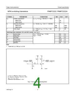
Vi = 9.5 V; T = 500 µs; tp = 10 µs; tr = tf ≤ 3 ns.
R1 = 68 Ω; R2 = 325 Ω; RB = 325 Ω; RC = 160 Ω.
VBB = −3.5 V; VCC = 29.5 V.
Oscilloscope: input impedance Zi = 50 Ω.
Fig.2 Test circuit for switching times.
1999 Apr 27
4

 NXP [ NXP ]