Philips Semiconductors
Product specification
Clock/calendar with 240 × 8-bit RAM
PCF8583
handbook, full pagewidth
START
CONDITION
(S)
BIT 7
MSB
(A7)
BIT 6
(A6)
BIT 0
LSB
(R/W)
ACKNOWLEDGE
(A)
STOP
CONDITION
(P)
PROTOCOL
t
t
t
HIGH
SU;STA
LOW
1 / f
SCL
SCL
SDA
t
t
t
f
BUF
r
t
t
t
t
t
HD;STA
SU;DAT
VD;DAT
SU;STO
HD;DAT
MBD820
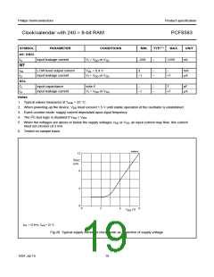
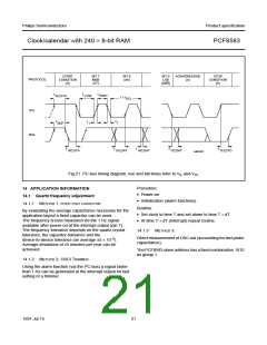
Fig.21 I2C-bus timing diagram; rise and fall times refer to VIL and VIH.
Procedure:
14 APPLICATION INFORMATION
14.1 Quartz frequency adjustment
14.1.1 METHOD 1: FIXED OSCI CAPACITOR
• Power-on
• Initialization (alarm functions).
Routine:
By evaluating the average capacitance necessary for the
application layout a fixed capacitor can be used.
The frequency is best measured via the 1 Hz signal
available after power-on at the interrupt output (pin 7).
The frequency tolerance depends on the quartz crystal
tolerance, the capacitor tolerance and the
device-to-device tolerance (on average ±5 × 10⁻⁶).
Average deviations of ±5 minutes per year can be
achieved.
• Set clock to time T and set alarm to time T + dT
• At time T + dT (interrupt) repeat routine.
14.1.3
METHOD 3:
Direct measurement of OSC out (accounting for test probe
capacitance).
The PCF8583 slave address has a fixed combination 1010
as group 1.
14.1.2 METHOD 2: OSCI TRIMMER
Using the alarm function (via the I2C-bus) a signal faster
than 1 Hz can be generated at the interrupt output for fast
setting of a trimmer.
1997 Jul 15
21

 NXP [ NXP ]