Philips Semiconductors
Product specification
Single-chip 8-bit microcontroller
80C552/83C552
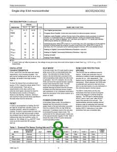
PIN DESCRIPTION (Continued)
PIN NO.
MNEMONIC
PLCC
36, 37
47
QFP
34-36
48
TYPE
NAME AND FUNCTION
V
SS
I
Two Digital ground pins.
PSEN
O
O
Program Store Enable: Active-low read strobe to external program memory.
ALE
EA
48
49
Address Latch Enable: Latches the low byte of the address during accesses to external
memory. It is activated every six oscillator periods. During an external data memory
access, one ALE pulse is skipped. ALE can drive up to eight LS TTL inputs and handles
CMOS inputs without an external pull-up.
49
50
I
External Access: When EA is held at TTL level high, the CPU executes out of the internal
program ROM provided the program counter is less than 8192. When EA is held at TTL
low level, the CPU executes out of external program memory. EA is not allowed to float.
AV
AV
AV
AV
58
59
60
61
59
60
61
63
I
I
I
I
Analog to Digital Conversion Reference Resistor: Low-end.
Analog to Digital Conversion Reference Resistor: High-end.
Analog Ground
REF–
REF+
SS
Analog Power Supply
DD
NOTE:
1. To avoid “latch-up” effect at power-on, the voltage on any pin at any time must not be higher or lower than V + 0.5V or V – 0.5V,
DD
SS
respectively.
OSCILLATOR
CHARACTERISTICS
XTAL1 and XTAL2 are the input and output,
respectively, of an inverting amplifier. The
pins can be configured for use as an on-chip
oscillator, as shown in the logic symbol,
page 2.
IDLE MODE
ROM CODE PROTECTION
(83C552)
In the idle mode, the CPU puts itself to sleep
while some of the on-chip peripherals stay
active. The instruction to invoke the idle
mode is the last instruction executed in the
normal operating mode before the idle mode
is activated. The CPU contents, the on-chip
RAM, and all of the special function registers
remain intact during this mode. The idle
mode can be terminated either by any
enabled interrupt (at which time the process
is picked up at the interrupt service routine
and continued), or by a hardware reset which
starts the processor in the same manner as a
power-on reset.
The 83C552 has an additional security
feature. ROM code protection may be
selected by setting a mask–programmable
security bit (i.e., user dependent). This
feature may be requested during ROM code
submission. When selected, the ROM code
is protected and cannot be read out at any
time by any test mode or by any instruction in
the external program memory space.
To drive the device from an external clock
source, XTAL1 should be driven while XTAL2
is left unconnected. There are no
requirements on the duty cycle of the
external clock signal, because the input to
the internal clock circuitry is through a
divide-by-two flip-flop. However, minimum
and maximum high and low times specified in
the data sheet must be observed.
The MOVC instructions are the only
instructions that have access to program
code in the internal or external program
memory. The EA input is latched during
RESET and is “don’t care” after RESET
(also if the security bit is not set). This
implementation prevents reading internal
program code by switching from external
program memory to internal program memory
during a MOVC instruction or any other
instruction that uses immediate data.
POWER-DOWN MODE
In the power-down mode, the oscillator is
stopped and the instruction to invoke
power-down is the last instruction executed.
Only the contents of the on-chip RAM are
preserved. A hardware reset is the only way
to terminate the power-down mode. The
control bits for the reduced power modes are
in the special function register PCON. Table 1
shows the state of the I/O ports during low
current operating modes.
RESET
A reset is accomplished by holding the RST
pin high for at least two machine cycles (24
oscillator periods), while the oscillator is
running. To insure a good power-on reset, the
RST pin must be high long enough to allow
the oscillator time to start up (normally a few
milliseconds) plus two machine cycles. At
power-on, the voltage on V and RST must
come up at the same time for a proper
start-up.
DD
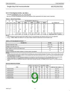
Table 1. External Pin Status During Idle and Power-Down Modes
PROGRAM
MEMORY
PWM0/
PWM1
MODE
Idle
ALE
PSEN
PORT 0
Data
PORT 1
Data
PORT 2
Data
PORT 3
Data
PORT 4
Data
Internal
1
1
0
0
1
1
0
0
1
1
1
1
Idle
External
Internal
Float
Data
Address
Data
Data
Data
Power-down
Power-down
Data
Data
Data
Data
External
Float
Data
Data
Data
Data
8
1998 Aug 13

 NXP [ NXP ]