PCA9675
NXP Semiconductors
Remote 16-bit I/O expander for Fm+ I2C-bus with interrupt
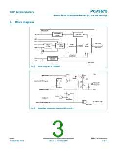
5. Block diagram
PCA9675
INTERRUPT
LP FILTER
LOGIC
INT
AD0
AD1
AD2
P00 to P07
SCL
SDA
2
SHIFT
REGISTER
I/O
PORT
INPUT
FILTER
I C-BUS
16 BITS
CONTROL
P10 to P17
write pulse
read pulse
POWER-ON
RESET
V
DD
V
SS
002aab627
Fig 1. Block diagram of PCA9675
V
DD
I
I
OH
write pulse
100 μA
I
trt(pu)
D
Q
data from Shift Register
power-on reset
P00 to P07
P10 to P17
FF
S
OL
CI
V
SS
D
Q
FF
S
CI
read pulse
to interrupt logic
data to Shift Register
002aab631
Fig 2. Simplified schematic diagram of P00 to P17
PCA9675
All information provided in this document is subject to legal disclaimers.
© NXP B.V. 2011. All rights reserved.
Product data sheet
Rev. 2 — 3 October 2011
3 of 34

 NXP [ NXP ]