Philips Semiconductors
Preliminary specification
80C51 8-bit microcontroller
8K/256 OTP, 8 channel 10 bit A/D, I2C, PWM,
capture/compare, high I/O, low voltage (2.7V–5.5V), low power
P87C552
MASTER TRANSMITTER AND MASTER RECEIVER MODES
The master mode is entered in the main program. To enter the
master transmitter mode, the main program must first load the
internal data RAM with the slave address, data bytes, and the
number of data bytes to be transmitted. To enter the master receiver
mode, the main program must first load the internal data RAM with
the slave address and the number of data bytes to be received. The
R/W bit determines whether SIO1 operates in the master transmitter
or master receiver mode.
Master mode operation commences when the STA bit in S1CION is
set by the SETB instruction and data transfer is controlled by the
master state service routines in accordance with Table 6, Table 7,
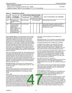
Figure 39, and Figure 40. In the example below, 4 bytes are
transferred. There is no repeated START condition. In the event of
lost arbitration, the transfer is restarted when the bus becomes free.
2
If a bus error occurs, the I C bus is released and SIO1 enters the
not selected slave receiver mode. If a slave device returns a not
acknowledge, a STOP condition is generated.
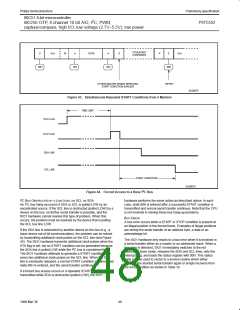
A repeated START condition can be included in the serial transfer if
the STA flag is set instead of the STO flag in the state service
routines vectored to by status codes 28H and 58H. Additional
software must be written to determine which data is transferred after
a repeated START condition.
SLAVE TRANSMITTER AND SLAVE RECEIVER MODES
2
After initialization, SIO1 continually tests the I C bus and branches
to one of the slave state service routines if it detects its own slave
address or the general call address (see Table 8, Table 9, Figure 41,
and Figure 42). If arbitration was lost while in the master mode, the
master mode is restarted after the current transfer. If a bus error
2
occurs, the I C bus is released and SIO1 enters the not selected
slave receiver mode.
In the slave receiver mode, a maximum of 8 received data bytes can
be stored in the internal data RAM. A maximum of 8 bytes ensures
that other RAM locations are not overwritten if a master sends more
bytes. If more than 8 bytes are transmitted, a not acknowledge is
returned, and SIO1 enters the not addressed slave receiver mode. A
maximum of one received data byte can be stored in the internal
data RAM after a general call address is detected. If more than one
byte is transmitted, a not acknowledge is returned and SIO1 enters
the not addressed slave receiver mode.
In the slave transmitter mode, data to be transmitted is obtained
from the same locations in the internal data RAM that were
previously loaded by the main program. After a not acknowledge
has been returned by a master receiver device, SIO1 enters the not
addressed slave mode.
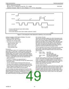
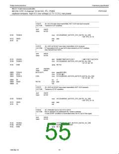
ADAPTING THE SOFTWARE FOR DIFFERENT APPLICATIONS
The following software example shows the typical structure of the
interrupt routine including the 26 state service routines and may be
used as a base for user applications. If one or more of the four
modes are not used, the associated state service routines may be
removed but, care should be taken that a deleted routine can never
be invoked.
This example does not include any time-out routines. In the slave
modes, time-out routines are not very useful since, in these modes,
SIO1 behaves essentially as a passive device. In the master modes,
an internal timer may be used to cause a time-out if a serial transfer
is not complete after a defined period of time. This time period is
2
defined by the system connected to the I C bus.
51
1999 Mar 30

 NXP [ NXP ]